An environmental protection sludge separation device

A separation device and environmental protection technology, applied in the direction of sludge treatment, water/sludge/sewage treatment, water/sewage treatment, etc., can solve the problem that sludge is prone to bacteria, equipment dry block sludge affects equipment separation Efficiency, the scope of equipment work and other issues, to achieve the effect of increasing stability, enhancing disinfection effect, and speeding up the filtration rate

Active Publication Date: 2022-03-22
临沂朝日电子有限公司
View PDF12 Cites 0 Cited by
  • Summary
  • Abstract
  • Description
  • Claims
  • Application Information

AI Technical Summary

Problems solved by technology

[0005] Aiming at the deficiencies of the prior art, the present invention provides an environmental protection sludge separation device, which solves the problem that bacteria are easily generated inside the sludge during the separation work, and some sludge with peculiar smell can affect the working range of the equipment. Dry blocky sludge is prone to appear inside the equipment, which affects the efficiency of equipment separation

Method used


Image

  • An environmental protection sludge separation device
  • An environmental protection sludge separation device
  • An environmental protection sludge separation device

Examples


Embodiment 1

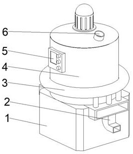
[0042] see Figure 1-6 , the present invention provides a technical solution: an environmental protection sludge separation device, including a static main body 1, through which the water contained in the sludge can be stored, and the static main body 1 performs storage during storage. The static sedimentation of the sewage reduces the situation that the discharged sewage still has a large amount of impurities. The middle position of the top of the outer wall on both sides of the static main body 1 is connected with a multi-layer discharge box 2, which is separated by the multi-layer discharge box 2. The sewage and sludge are discharged at different positions, thereby avoiding the re-mixing of sludge and sewage during discharge, and the multi-layer discharge box 2 is not easy to be blocked when discharging, effectively speeding up the discharge of sewage The top of the static main body 1 is fixedly connected with the processing device 4, the bottom of the processing device 4 r...

Embodiment 2

[0049] see Figure 1-6 , on the basis of Embodiment 1, the present invention provides a technical solution: a method for using an environmental protection sludge separation device, which is characterized in that: Step 1: The equipment is installed, and the static main body 1 and the multi-layer outlet The material box 2 is communicated, the processing device 4 is connected with the energy source, the processing device 4 is communicated with the feed pipe 6, and the static main body 1 is communicated with the processing device 4;

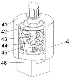
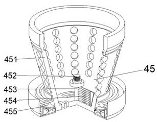
[0050] Step 2: When the sludge enters the separation tank 41 through the elastic barrier plate 42, it is tilted by the pressure of the sludge, so that the sludge falls into the filter device 45, and the rotating shaft 43 is driven by the motor to rotate, and Utilize the separating rod 44 that is connected on the rotating shaft 43 to pulverize the massive sludge that it contacts, and the separating tank 41 is fixedly connected with the filtering devic...


PUM


Abstract

The invention discloses an environmental protection sludge separation device, which relates to the technical field of sludge separation, and comprises a static main body. The middle position of the top of the outer wall on both sides of the static main body is connected with a multi-layer discharge box. The static main body The top of the processing device is fixedly connected with a processing device, and the bottom of the processing device runs through the static main body and extends to the inside of the static main body. A control panel is fixedly connected, and the top right side of the processing device communicates with a feed pipe. The environmental protection sludge separation device effectively speeds up the discharge of sewage. The separation rod rotates under the drive of the rotating shaft, so that the sludge that comes into contact with the inside of the filter device is driven by the elastic blocking plate with the rotating shaft. Rotate, and the elastic blocking plate first contacts the sludge entering the separation tank, and the elastic blocking plate is inclined under the pressure of the sludge.

Description

technical field [0001] The invention relates to the technical field of sludge separation, in particular to an environmental protection sludge separation device. Background technique [0002] Sludge contains a large number of microorganisms and a large number of substances beneficial to plants. In order to facilitate the use of sludge, sludge is usually dried and transported, and the dried sludge is used as planting soil for flowers and plants. Wet treatment can plant flowers and plants and provide nutrients for the planting of flowers and plants. Sewage often contains a lot of sludge, and sludge is prone to odor if it is not cleaned for a long time. [0003] According to an environmental protection sludge separation device disclosed in Chinese Patent No. CN111704342A, the rotating rod driven by the motor can make the propulsion plate drive the sludge forward, and the device can be easily pushed by the setting of the wheels, and the sludge can be driven through the extrusion ...

Claims


Application Information

Patent Timeline
Patent Type & Authority Patents(China)
IPC IPC(8): C02F11/121C02F11/00C02F9/08
CPCC02F11/121C02F11/00C02F9/00C02F1/001C02F2001/007C02F1/283C02F1/325C02F2303/04C02F2303/02
Inventor 朱中林刘鲁子
Owner 临沂朝日电子有限公司
Why Eureka
Try Eureka