Spinning device and spinning method

A technology of processing device and small diameter part, which is applied in the direction of engine components, cylinders, mechanical equipment, etc., and can solve problems such as strength reduction

Pending Publication Date: 2022-01-07
NIHON SPINDLE MFG CO LTD
View PDF2 Cites 0 Cited by
  • Summary
  • Abstract
  • Description
  • Claims
  • Application Information

AI Technical Summary

Problems solved by technology

It is known that when the flange is formed by processing a cylindrical base material, t

Method used


Image

  • Spinning device and spinning method
  • Spinning device and spinning method
  • Spinning device and spinning method

Examples


no. 1 Embodiment approach >

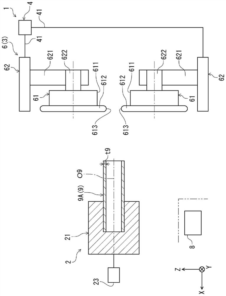
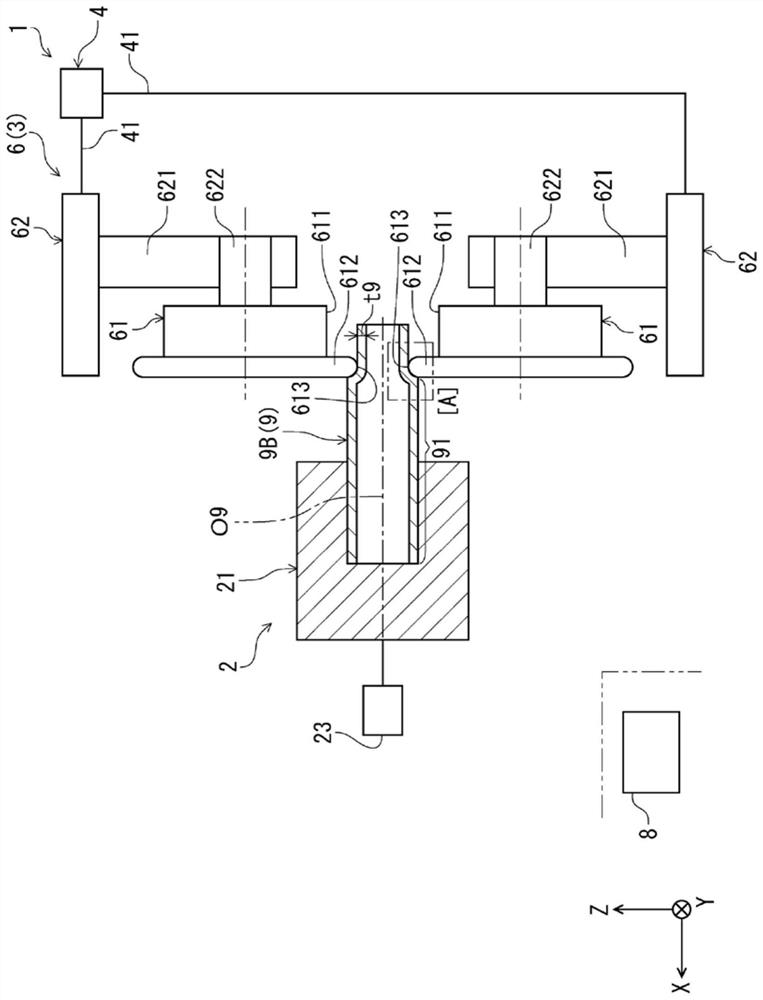
[0029] Below, refer to Figure 1 to Figure 8 A first embodiment of the spinning device and spinning method of the present invention will be described. In addition, in the following, for convenience of description, three axes orthogonal to each other are respectively set as an X axis, a Y axis, and a Z axis. As an example, the XY plane including the X axis and the Y axis is a horizontal plane, and the Z axis is a vertical axis. and, sometimes Figure 1 to Figure 6 middle( Figure 9 and Figure 10 The upper side is called "upper (or upper)" and the lower side is called "lower (or lower)".

[0030] like Figure 1 ~ Figure 4 As shown, the spinning machine 1 includes a rotation support unit 2 , a processing unit 3 , a first moving mechanism unit 4 , and a second moving mechanism unit 5 . The spinning apparatus 1 can form a base material 9 to obtain a molded product 9C from the base material 9 . Also, the molded product 9C is used, for example, as a shaft.

[0031] and, if ...

no. 2 Embodiment approach >

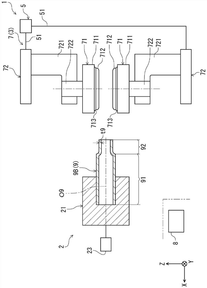
[0086] Below, refer to Figure 9 and Figure 10 The second embodiment of the spinning device and spinning method of the present invention will be described, but the description will focus on the differences from the above-mentioned embodiment, and the description of the same configuration will be omitted.

[0087] This embodiment is the same as the above-mentioned 1st Embodiment except the structure of the rotation support part 2 being different.

[0088] In this embodiment, the rotation support part 2 can be switched between the first connection state connected to the first molding part 6 and the second connection state connected to the second molding part 7 by a switching mechanism (not shown).

[0089] Moreover, in the first connection state, such as Figure 9 As shown, the rotation support part 2 is capable of rotating the first molding part 6 around the base material 9 (central axis O9 ) with respect to the base material 9 in a state in which the base material 9 is fixe...


PUM


Abstract

Provided are a spinning device and a spinning method which, when forming a flange on a cylindrical base material, make it possible to easily form the flange while maintaining the wall thickness of the base material. This spinning device (1) comprises a flange forming unit (a second forming unit (7) which, while a base material that has a large-diameter part (91) and a small-diameter part (92) is being rotated relative thereto, presses and deforms the large-diameter part (91) in the direction of the central axis (O9) while contacting the outer periphery of the small-diameter part (92), thereby forming a flange (93) that projects in the direction away from the central axis (O9) on the large-diameter part (91).

Description

[0001] This application claims priority based on Japanese Patent Application No. 2020-116155 filed on July 06, 2020. The entire content of this Japanese application is incorporated in this specification by reference. technical field [0002] The invention relates to a spinning processing device and a spinning processing method. Background technique [0003] Examples of automotive parts include shafts. The shaft is sometimes obtained by processing a cylindrical base material. [0004] Patent Document 1 discloses a spinning machine for thinning a cylindrical base material (work). This spinning machine includes rotating rollers for thinning the outer peripheral wall portion of the base material by thinning and stretching. [0005] Patent Document 1: Japanese Patent Laid-Open No. 2011-115813 [0006] However, if a thinned member is used as a shaft, since the strength (deformation resistance) of the member decreases with thinning, it may be difficult to withstand the actual u...

Claims


Application Information

Patent Timeline
IPC IPC(8): B21D22/16
CPCB21D22/16B21D22/18B21D41/04B21D15/04B21D19/046B21H1/20
Inventor 高田佳昭
Owner NIHON SPINDLE MFG CO LTD
Why Eureka
Try Eureka