Optical lens, camera module and electronic equipment

An optical lens and lens technology, applied in optics, optical components, instruments, etc., to achieve the effect of blurring the background, improving imaging quality, and ensuring telephoto characteristics

Active Publication Date: 2022-03-04
JIANGXI JINGCHAO OPTICAL CO LTD
View PDF3 Cites 2 Cited by
  • Summary
  • Abstract
  • Description
  • Claims
  • Application Information

AI Technical Summary

Problems solved by technology

[0002] At present, with the development of camera technology, optical lenses are more and more widely used in electronic devices such as smartphones, tablet computers, and video phones, such as taking pictures, taking pictures, or making video calls. The volume and imaging quality requirements of optical lenses are getting higher and higher. However, in related technologies, optical lenses cannot meet the design requirements of miniaturization and high imaging quality while having a long focal length.

Method used


Image

  • Optical lens, camera module and electronic equipment
  • Optical lens, camera module and electronic equipment
  • Optical lens, camera module and electronic equipment

Examples


no. 1 example

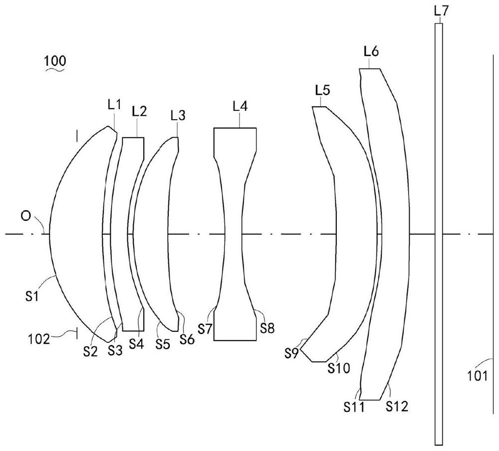
[0076] The structural diagram of the optical lens 100 disclosed in the first embodiment of the present application is as follows figure 1 As shown, the optical lens 100 includes a stop 102, a first lens L1, a second lens L2, a third lens L3, a fourth lens L4, a fifth lens L5, a first lens L1, a fourth lens L4, a fifth lens L5, and a first lens L1 arranged sequentially from the object side to the image side along the optical axis O. Six lenses L6 and filter L7, the first lens L1 has positive refractive power, the second lens L2 has negative refractive power, the third lens L3 has positive refractive power, the fourth lens L4 has negative refractive power, and the fifth lens L5 has Positive refractive power, the sixth lens L6 has negative refractive power.

[0077] Further, the object side S1 and the image side S2 of the first lens L1 are respectively convex and concave at the near optical axis O, the object side S1 and the image side S2 of the first lens L1 are respectively con...

no. 2 example

[0099] Please refer to Figure 5 , Figure 5 It is a schematic structural diagram of the optical lens 100 according to the second embodiment of the present application. The optical lens 100 includes a diaphragm 102, a first lens L1, a second lens L2, a third lens L3, a fourth lens L4, a fifth lens L5, and a sixth lens L6 arranged in sequence from the object side to the image side along the optical axis O And filter L7, the first lens L1 has a positive refractive power, the second lens L2 has a negative refractive power, the third lens L3 has a positive refractive power, the fourth lens L4 has a negative refractive power, and the fifth lens L5 has a positive refractive power , the sixth lens L6 has a negative refractive power.

[0100] Further, the object side S1 and the image side S2 of the first lens L1 are respectively convex and concave at the near optical axis O, the object side S1 and the image side S2 of the first lens L1 are respectively convex and concave at the circ...

no. 3 example

[0111] Please refer to Figure 7 , Figure 7 It is a schematic structural diagram of the optical lens 100 according to the third embodiment of the present application. The optical lens 100 includes a diaphragm 102, a first lens L1, a second lens L2, a third lens L3, a fourth lens L4, a fifth lens L5, and a sixth lens L6 arranged in sequence from the object side to the image side along the optical axis O And filter L7, the first lens L1 has a positive refractive power, the second lens L2 has a negative refractive power, the third lens L3 has a positive refractive power, the fourth lens L4 has a negative refractive power, and the fifth lens L5 has a positive refractive power , the sixth lens L6 has a negative refractive power.

[0112] Further, the object side S1 and the image side S2 of the first lens L1 are respectively convex and concave at the near optical axis O, the object side S1 and the image side S2 of the first lens L1 are respectively convex and concave at the circu...


PUM

PropertyMeasurementUnit
lengthaaaaaaaaaa
optical path lengthaaaaaaaaaa

Abstract

The invention discloses an optical lens, a camera module and an electronic device, the optical lens comprises a first lens, a second lens, a third lens, a fourth lens, a fifth lens and a sixth lens which are sequentially arranged from an object side to an image side along an optical axis, the first lens has positive refractive power, the second lens has negative refractive power, the third lens has positive refractive power, the fourth lens has negative refractive power, and the sixth lens has positive refractive power. The fourth lens has negative refractive power, the fifth lens has positive refractive power, the sixth lens has negative refractive power, and the optical lens meets the following relational expressions: 45.5 < = f * 43 / ImgH < 61.0; wherein f is the effective focal length of the optical lens, and ImgH is the image height corresponding to the maximum field angle of the optical lens. According to the optical lens, the camera module and the electronic equipment provided by the invention, the optical lens has a long focal length, meanwhile, the miniaturization design requirement is met, and the imaging quality is improved.

Description

technical field [0001] The invention relates to the technical field of optical imaging, in particular to an optical lens, a camera module and electronic equipment. Background technique [0002] At present, with the development of camera technology, optical lenses are more and more widely used in electronic devices such as smartphones, tablet computers, and video phones, such as taking pictures, taking pictures, or making video calls. The volume and imaging quality requirements of the optical lens are getting higher and higher. However, in related technologies, the optical lens cannot meet the design requirements of miniaturization and high imaging quality while having a long focal length. Contents of the invention [0003] The embodiment of the present invention discloses an optical lens, a camera module and electronic equipment, which can make the optical lens have a long focal length, meet the design requirements of miniaturization, and improve the imaging quality. [0...

Claims


Application Information

Patent Timeline
Patent Type & Authority Applications(China)
IPC IPC(8): G02B13/00G02B13/18G02B13/14
CPCG02B13/0015G02B13/0045G02B13/008G02B13/14G03B30/00
Inventor 王国贵杨健李明
Owner JIANGXI JINGCHAO OPTICAL CO LTD
Why Eureka
Try Eureka