

Camera lens
A camera lens and lens technology, applied in the field of camera lens, can solve the problems of not being able to display the scene well, increasing the total length and design difficulty of the camera lens, restricting the miniaturization design of the camera lens, etc., so as to achieve miniaturized imaging quality and good imaging quality. , the effect of optimizing optical parameters
- Summary
- Abstract
- Description
- Claims
- Application Information
AI Technical Summary
Problems solved by technology
Method used
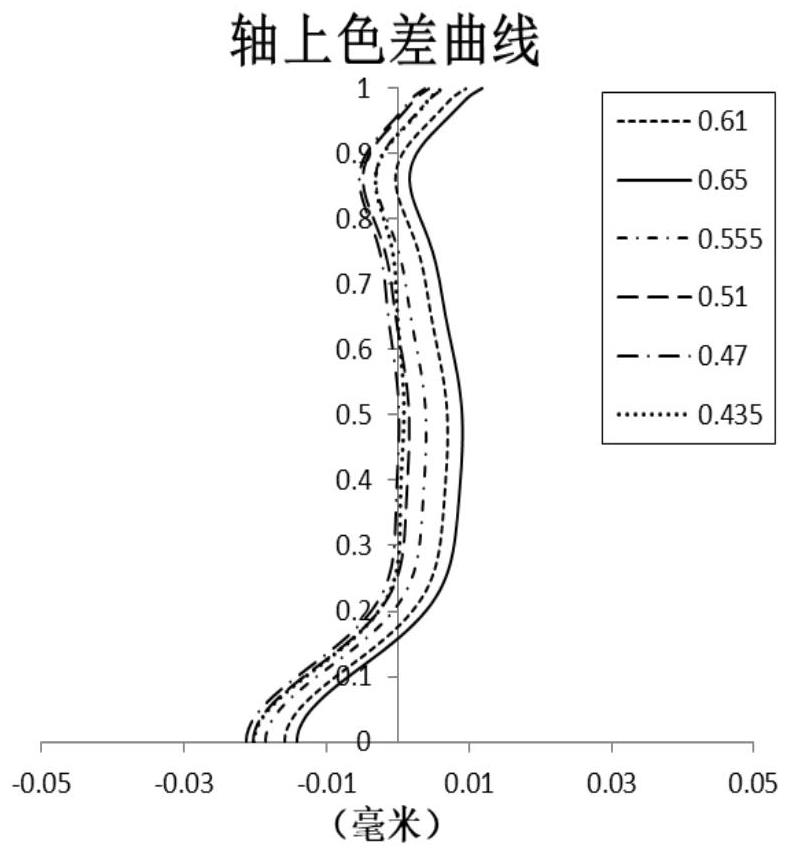
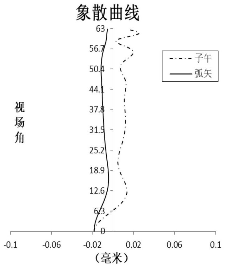
Image

Examples
Embodiment 1
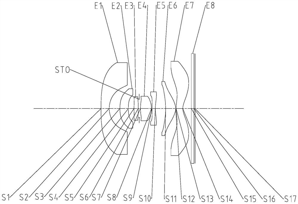
[0075] Refer to the following Figure 1 to Figure 2C An imaging lens according to Embodiment 1 of the present application will be described. figure 1 A schematic structural diagram of an imaging lens according to Embodiment 1 of the present application is shown.
[0076] Such as figure 1 As shown, the imaging lens includes in sequence from the object side to the image side: the first lens E1, the second lens E2, the third lens E3, the diaphragm STO, the fourth lens E4, the fifth lens E5, the sixth lens E6, the Seven lenses E7, filter E8 and imaging surface S17.
[0077] The first lens E1 has negative refractive power, its object side S1 is convex, and its image side S2 is concave. The second lens E2 has positive refractive power, its object side S3 is convex, and its image side S4 is concave. The third lens E3 has positive refractive power, its object side S5 is convex, and its image side S6 is convex. The fourth lens E4 has positive refractive power, its object side S7 i...
Embodiment 2
[0091] Refer to the following Figure 3 to Figure 4C An imaging lens according to Embodiment 2 of the present application will be described. In this embodiment and the following embodiments, for the sake of brevity, descriptions similar to those in Embodiment 1 will be omitted. image 3 A schematic structural diagram of an imaging lens according to Embodiment 2 of the present application is shown.
[0092] Such as image 3 As shown, the imaging lens includes in sequence from the object side to the image side: the first lens E1, the second lens E2, the third lens E3, the diaphragm STO, the fourth lens E4, the fifth lens E5, the sixth lens E6, the Seven lenses E7, filter E8 and imaging surface S17.
[0093] The first lens E1 has negative refractive power, its object side S1 is convex, and its image side S2 is concave. The second lens E2 has positive refractive power, its object side S3 is convex, and its image side S4 is concave. The third lens E3 has positive refractive po...
Embodiment 3
[0105] Refer to the following Figure 5 to Figure 6C An imaging lens according to Embodiment 3 of the present application is described. Figure 5 A schematic structural diagram of an imaging lens according to Embodiment 3 of the present application is shown.
[0106] Such as Figure 5 As shown, the imaging lens includes in sequence from the object side to the image side: the first lens E1, the second lens E2, the third lens E3, the diaphragm STO, the fourth lens E4, the fifth lens E5, the sixth lens E6, the Seven lenses E7, filter E8 and imaging surface S17.
[0107] The first lens E1 has negative refractive power, its object side S1 is convex, and its image side S2 is concave. The second lens E2 has positive refractive power, its object side S3 is convex, and its image side S4 is concave. The third lens E3 has positive refractive power, its object side S5 is convex, and its image side S6 is concave. The fourth lens E4 has positive refractive power, its object side S7 is ...
PUM
 Abstract
Description
Claims
Application Information