Optical system, camera module and electronic equipment

An optical system and optical axis technology, applied in optics, optical components, instruments, etc., can solve the problems of narrow viewing angle of the optical system, inability to accurately judge the details of long-distance shooting in real time, low resolution, etc., and achieve good imaging quality. Effect

Active Publication Date: 2021-10-08
JIANGXI JINGCHAO OPTICAL CO LTD
View PDF6 Cites 0 Cited by
  • Summary
  • Abstract
  • Description
  • Claims
  • Application Information

AI Technical Summary

Problems solved by technology

However, the resolution of the optical system in the existing front-view camera module is low, and it is impossible to accurately judge the details of long-distance shooting in real time and make an early warning, and the viewing angle of the optical system in the existing front-view camera module is narrow, which is difficult Transmits a wide range of driving environments more clearly to the system for recognition

Method used


Image

  • Optical system, camera module and electronic equipment
  • Optical system, camera module and electronic equipment
  • Optical system, camera module and electronic equipment

Examples


Embodiment 1

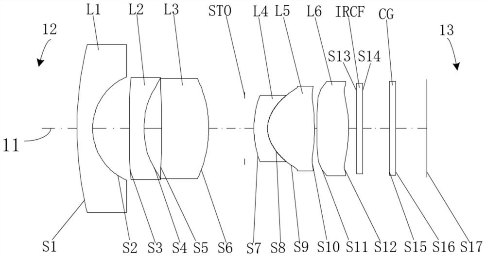
[0050] Such as figure 1 As shown, the straight line 11 represents the optical axis, the side of the first lens L1 away from the second lens L2 is the object side 12 , and the side of the sixth lens L6 away from the fifth lens L5 is the image side 13 . In the optical system provided by this embodiment, the first lens L1, the second lens L2, the third lens L3, the stop STO, the fourth lens L4, the fifth lens L5, the Six lenses L6, infrared filter IRCF, protective glass CG.

[0051] The first lens L1 has a negative refractive power and is made of glass. The object side S1 is convex at the near optical axis, and the image side S2 is concave at the near optical axis, both of which are spherical.

[0052] The second lens L2 has a negative refractive power and is made of plastic. The object side S3 and the image side S4 of the second lens L2 are both concave and aspherical at the near optical axis.

[0053] The third lens L3 has a positive refractive power and is made of glass. Its...

Embodiment 2

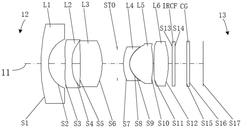
[0076] Such as image 3 As shown, the straight line 11 represents the optical axis, the side of the first lens L1 away from the second lens L2 is the object side 12 , and the side of the sixth lens L6 away from the fifth lens L5 is the image side 13 . In the optical system provided by this embodiment, the first lens L1, the second lens L2, the third lens L3, the stop STO, the fourth lens L4, the fifth lens L5, the Six lenses L6, infrared filter IRCF, protective glass CG.

[0077] The first lens L1 has a negative refractive power and is made of glass. The object side S1 is convex at the near optical axis, and the image side S2 is concave at the near optical axis, both of which are spherical.

[0078] The second lens L2 has a negative refractive power and is made of plastic. The object side S3 and the image side S4 of the second lens L2 are both concave and aspherical at the near optical axis.

[0079] The third lens L3 has a positive refractive power and is made of glass. Its...

Embodiment 3

[0098] Such as Figure 5 As shown, the straight line 11 represents the optical axis, the side of the first lens L1 away from the second lens L2 is the object side 12 , and the side of the sixth lens L6 away from the fifth lens L5 is the image side 13 . In the optical system provided by this embodiment, the first lens L1, the second lens L2, the third lens L3, the stop STO, the fourth lens L4, the fifth lens L5, the Six lenses L6, infrared filter IRCF, protective glass CG.

[0099] The first lens L1 has a negative refractive power and is made of glass. The object side S1 is convex at the near optical axis, and the image side S2 is concave at the near optical axis, both of which are spherical.

[0100] The second lens L2 has a negative refractive power and is made of plastic. The object side S3 and the image side S4 of the second lens L2 are both concave and aspherical at the near optical axis.

[0101] The third lens L3 has a positive refractive power and is made of glass. Th...


PUM


Abstract

The embodiment of the invention discloses an optical system, a camera module and electronic equipment. The optical system includes a first lens and a second lens having negative refractive power, a third lens and a sixth lens having positive refractive power, and a fourth lens and a fifth lens having refractive power. The object-side surface of the second lens is a concave surface in a paraxial region, the object-side surface of the fourth lens is a convex surface in a paraxial region, and the object-side surface and the image-side surface of the sixth lens are convex surfaces in paraxial regions. The optical system meets the following conditional expression: 84.5 degrees/mm < FOV/EPD < 99 degrees/mm, wherein FOV is the maximum field angle of the optical system, and EPD is the entrance pupil diameter of the optical system. By reasonably configuring the refractive power of the first lens to the sixth lens, the surface types of the second lens, the fourth lens and the sixth lens and limiting the FOV/EPD range, the optical system has the characteristics of ultra-wide angle and large aperture and has good imaging quality.

Description

technical field [0001] The present application belongs to the technical field of optical imaging, and in particular relates to an optical system, a camera module and electronic equipment. Background technique [0002] With the development of the vehicle industry, the technical requirements for vehicle camera modules such as front view, advanced driver assistance systems, driving recorders, and reversing images are getting higher and higher. The forward-looking camera module is assembled in front of the vehicle and provides functions such as lane departure warning, automatic lane keeping assist, high / low beam control and traffic sign recognition. [0003] When the front-view camera module is used in parking, it can intuitively see the obstacles in front of the vehicle, making parking more convenient. In addition, the front-view camera module can enable the vehicle to turn on the front-view camera at any time when passing through special places (such as roadblocks, parking lo...

Claims


Application Information

Patent Timeline
Patent Type & Authority Applications(China)
IPC IPC(8): G02B13/00G02B13/06G02B13/18G03B30/00
CPCG02B13/0045G02B13/06G02B13/18G02B13/006G03B30/00
Inventor 乐宇明蔡雄宇董勇兵赵迪
Owner JIANGXI JINGCHAO OPTICAL CO LTD
Why Eureka
Try Eureka