Epidemic prevention disinfection safety door

A safety door and shell technology, which is applied in the field of epidemic prevention and disinfection safety doors, can solve the problems of low work efficiency and achieve the effects of improving work efficiency, comprehensive disinfection, and improving disinfection efficiency

Pending Publication Date: 2022-06-03
段宝
View PDF1 Cites 1 Cited by
  • Summary
  • Abstract
  • Description
  • Claims
  • Application Information

AI Technical Summary

Problems solved by technology

A disinfection door of the present invention can quickly disinfect personnel, improve the efficiency of disinfection, and has the advantage of a high degree of automation. Although the above patent can disinfect epidemic prevention personnel, there are only three atomizing nozzles to spray the disinfectant , lower work efficiency

Method used


Image

  • Epidemic prevention disinfection safety door
  • Epidemic prevention disinfection safety door
  • Epidemic prevention disinfection safety door

Examples


Embodiment 1

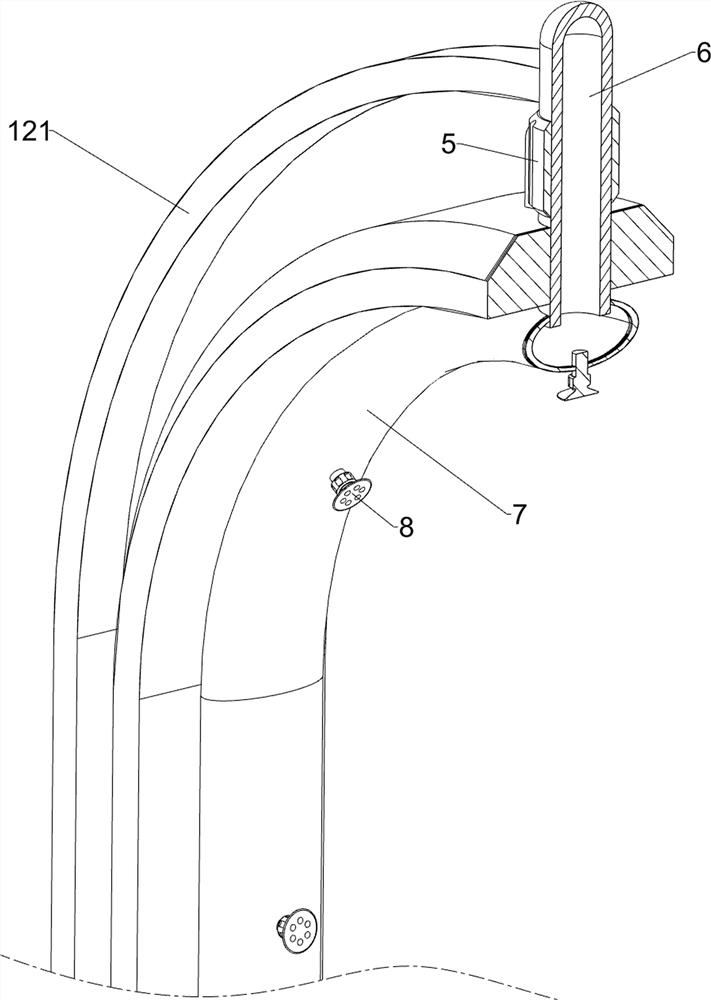
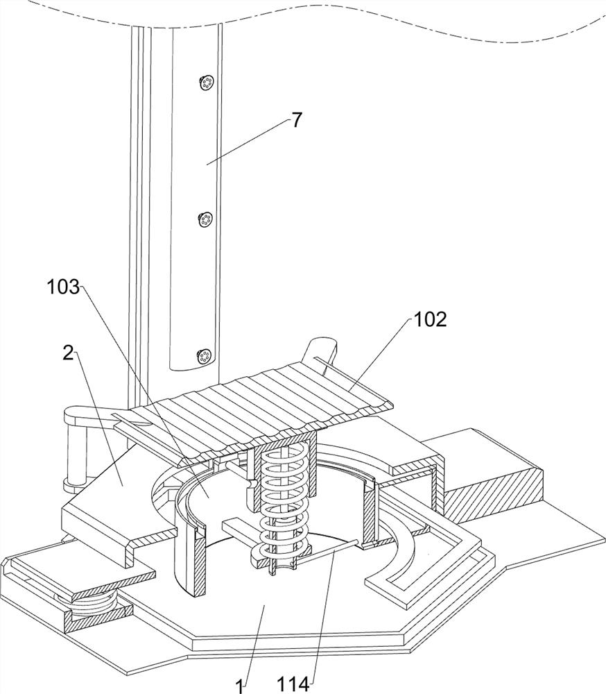
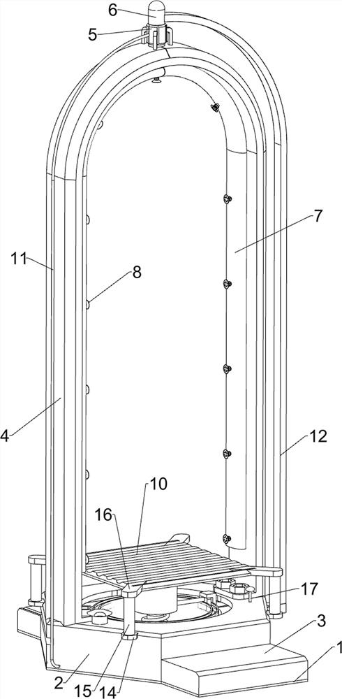
[0030] An epidemic prevention and disinfection safety door, comprising a bottom plate 1, a shell 2, a fixed seat 3, an n-type plate 4, a guide sleeve 5, a hollow rotating rod 6, an n-type pipe 7, an atomizing nozzle 8, a liquid storage tank 9, and a driving mechanism 10 and deflector 11, see figure 1 , figure 2 , image 3 , Figure 4 , Image 6 , Figure 7 and Figure 8 As shown, the shell 2 is installed in the middle of the top of the bottom plate 1 by welding, the top of the shell 2 is open, and the n-type plate 4 is installed between the middle parts of the left and right sides of the outer top of the shell 2 by bolts. A guide sleeve 5 is installed in the middle of the outer top of the n-type plate 4 by welding, a hollow rotating rod 6 is rotatably connected in the guide sleeve 5, and an n-type pipe 7 is installed at the bottom end of the hollow rotating rod 6 by welding. , the n-type pipe 7 is communicated with the hollow rotating rod 6, and there are seven atomizin...

Embodiment 2

[0037] On the basis of Embodiment 1, a rotating mechanism 12 is also included. The rotating mechanism 12 includes an L-shaped plate 121, a sliding plate 122, a sliding block 123, a contact rod 124 and an L-shaped block 125. Please refer to figure 1 , figure 2 , image 3 and Figure 5 As shown in the figure, a sliding block 123 is embedded in the top of the annular plate 103 and connected to the sliding block. The top of the sliding block 123 is mounted with an L-shaped block 125 by welding. The right end penetrates the right side of the housing 2, and the right side of the top of the slide plate 122 is installed with an L-shaped plate 121 by welding. , the L-shaped plate 121 can realize the reverse rotation of the hollow rotating rod 6, the upper part of the left side of the slider 123 is fixed with a contact rod 124, the outer side of the sleeve 101 is provided with a spiral groove 126, and the left end of the contact rod 124 is located in the spiral groove 126. When the ...

Embodiment 3

[0042] On the basis of Embodiment 1 and Embodiment 2, a guide sleeve 14, a guide rod 15 and a fixing plate 16 are also included. Please refer to figure 1 As shown in the figure, a guide sleeve 14 is installed on the upper part of the left and right sides of the housing 2 symmetrically by welding, and a guide rod 15 is slidably connected in the guide sleeve 14, and the four corners of the pedal 102 are connected by welding. A fixing plate 16 is installed, and the outer side of the bottom of the fixing plate 16 is fixedly connected with the top end of the guide rod 15 .

[0043] Also includes indicator rod 17 and floating plate 18, see figure 1 and image 3 As shown, a floating plate 18 is slidably placed in the liquid storage tank 9, and an indicator rod 17 is installed on the right rear of the top of the floating plate 18 by welding. Running through the front right side of the top of the housing 2 , the indicator rod 17 can be used to remind people of the amount of disinfect...


PUM


Abstract

The invention relates to a disinfection safety door, in particular to an epidemic prevention disinfection safety door. The invention relates to an epidemic prevention disinfection safety door which can simultaneously spray seven disinfectant to disinfect epidemic prevention personnel and is higher in working efficiency. An epidemic prevention disinfection safety door comprises a bottom plate, a shell, an n-shaped plate and the like, the shell is fixedly connected to the middle of the top of the bottom plate, the top of the shell is open, and the n-shaped plate is fixedly connected between the middles of the left side and the right side of the outer top of the shell. When an epidemic prevention person adheres to the driving mechanism, the driving mechanism operates to drive the flow guide mechanism to operate, the flow guide mechanism operates to discharge a disinfectant into the hollow rotating rod, the disinfectant in the hollow rotating rod is discharged into the n-shaped pipe, and the disinfectant in the n-shaped pipe is sprayed out through seven atomizing nozzles to disinfect the epidemic prevention person. And the seven atomizing nozzles can improve the disinfection efficiency of epidemic prevention personnel, so that the working efficiency is further improved.

Description

technical field [0001] The invention relates to a disinfection safety door, in particular to an epidemic prevention disinfection safety door. Background technique [0002] During the epidemic prevention process, some places will generally have epidemic prevention personnel to carry out epidemic prevention work, but after the epidemic prevention personnel get off work, in order to prevent the epidemic prevention personnel from spreading the virus to various places, the epidemic prevention personnel need to be disinfected after get off work. [0003] The Chinese patent with the application number CN202022438037.6 discloses a disinfection door, specifically, it is used in places with high traffic and dense crowds. The disinfection door includes: a door body, a spray head, a storage tank and a control mechanism; the door body is provided with a spray head; the storage tank is connected to the control mechanism and the spray head; the door body is also provided with a negative pr...

Claims


Application Information

Patent Timeline
Patent Type & Authority Applications(China)
IPC IPC(8): A61L2/22A61L2/26
CPCA61L2/0088A61L2/26A61L2202/15Y02A50/20
Inventor 段宝
Owner 段宝
Why Eureka
Try Eureka