Auxiliary device for welding main reinforcement of reinforcement cage and using method

An auxiliary device and reinforcement cage technology, applied in auxiliary devices, welding/cutting auxiliary equipment, welding equipment, etc., can solve the problems of burning clothes, health and safety hazards of construction workers, poor alignment effect, etc. Health and safety, high economic and social value, the effect of reducing labor usage

Pending Publication Date: 2022-06-03
MCC TIANGONG GROUP
View PDF0 Cites 0 Cited by
  • Summary
  • Abstract
  • Description
  • Claims
  • Application Information

AI Technical Summary

Problems solved by technology

[0002] Summing up the past construction experience, the traditional pile foundation construction needs to manually align the main bars of the upper and lower sections of the reinforcement cage for the connection of each section of the reinforcement cage when the reinforcement cage is installed. Welding, but the diameter of the main bars of the general steel cage is relatively large and the number is large. Manual symptomatic treatment is time-consuming and laborious, and the alignment effect is often not good. It is difficult to ensure that the upper and lower steel bars are in a concentric state, which has a great impact on the quality.
[0003]In addition, during the welder’s electric welding and fixing process, the righting personnel always need to keep stable and not let go, so that it is easy to cause damage to the health and safety of the construction personnel during spot welding. There are certain hazards, such as eye damage or burning clothes, and there are also certain safety risks, such as the electric shock risk of constructors caused by welding wire leakage

Method used


Image

  • Auxiliary device for welding main reinforcement of reinforcement cage and using method
  • Auxiliary device for welding main reinforcement of reinforcement cage and using method
  • Auxiliary device for welding main reinforcement of reinforcement cage and using method

Examples


Embodiment Construction

[0023] Embodiments of the present invention are described.

[0024] In order to make the objectives, technical solutions and advantages of the present invention clearer, the present invention will be further described in detail below with reference to the specific embodiments and the accompanying drawings. It should be understood that these descriptions are exemplary only and are not intended to limit the scope of the invention. Also, in the following description, descriptions of well-known structured techniques are omitted to avoid unnecessarily obscuring the concepts of the present invention.

[0025] Embodiments of the present invention will be described below with reference to the accompanying drawings.

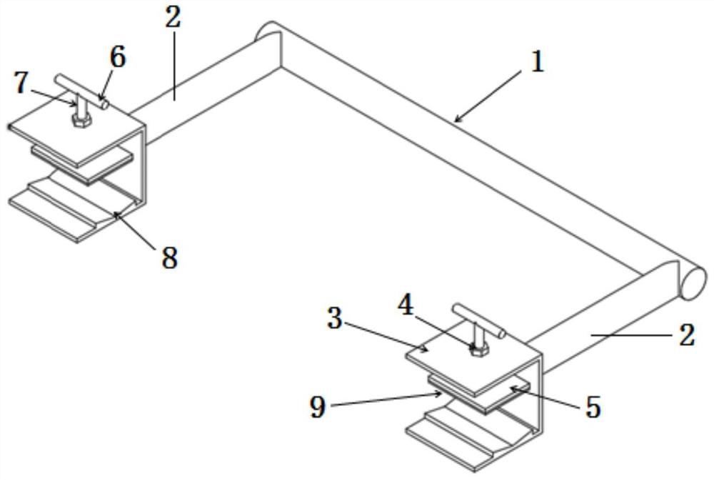
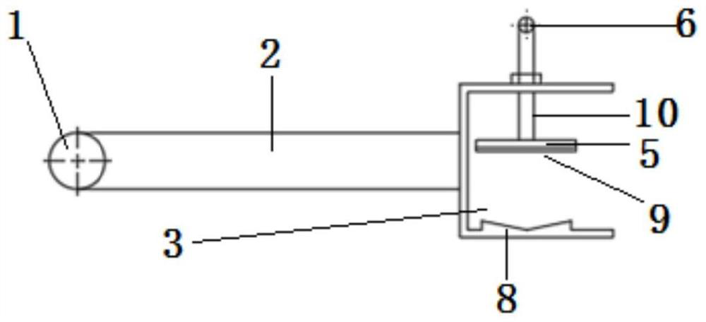
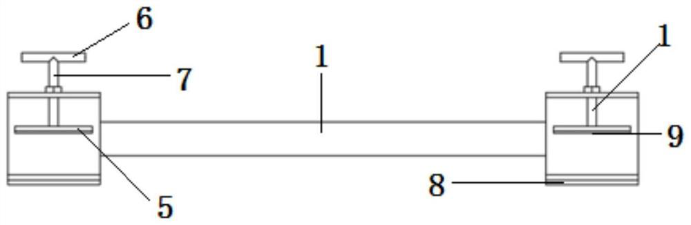
[0026] like figure 1 As shown in the figure, an auxiliary device and method of use for welding the main bars of a steel cage, including a holding rod 1, a support rod 2, a fixing device 3, an adjusting device 4, a pressing plate 5, an adjusting handle 6, a rotating shaf...


PUM


Abstract

The invention belongs to the field of building construction, and particularly relates to an auxiliary device for welding a main reinforcement of a reinforcement cage. Comprising a holding rod, supporting rods, an adjusting device and a fixing device, the supporting rods are symmetrically arranged at the two ends of the holding rod, the supporting rods are perpendicular to the holding rod, the fixing device is installed on the supporting rods and arranged at the ends, away from the holding rod, of the supporting rods, and the adjusting device is arranged on the fixing device. The main reinforcement of the reinforcement cage can be placed in the fixing device in a segmented mode, and the main reinforcement of the reinforcement cage is fixed and welded through the adjusting device. The device has the beneficial effects that operation is easy, time and labor are saved, reinforcing steel bar installation can be completed quickly with less labor and less time, meanwhile, it is guaranteed that upper and lower main reinforcing steel bars are overlapped and aligned to be in a concentric state, the labor utilization rate is greatly reduced, meanwhile, personnel safety is guaranteed, and the working efficiency is improved. The construction efficiency is effectively improved, pile foundation engineering is promoted to be harmoniously, uniformly and rapidly developed, cost optimization is achieved, and high economic and social values are achieved.

Description

technical field [0001] The invention belongs to the field of building construction, and in particular relates to an auxiliary device for welding the main bars of a steel cage and a method of using the same. Background technique [0002] Summarizing the previous construction experience, in the traditional pile foundation construction, when the reinforcement cage is installed, each section of the reinforcement cage needs to be lapped and welded after the main reinforcement of the upper and lower sections is manually aligned. , It is time-consuming and laborious to use manual symptomatic treatment, and the alignment effect is often poor, and it is difficult to ensure that the upper and lower steel bars are in a concentric state, which has a great impact on the quality. [0003] In addition, in the process of welding and fixing it by the welder, the righting personnel always need to keep stable and can not let go, so it is easy to cause certain harm to the health and safety of t...

Claims


Application Information

Patent Timeline
Patent Type & Authority Applications(China)
IPC IPC(8): B23K37/04
CPCB23K37/0443
Inventor 付长龙刘勇高文密王海风
Owner MCC TIANGONG GROUP
Why Eureka
Try Eureka