Shunt valve and cleaning machine applying shunt valve

A water separation valve and washing machine technology, which is applied to the parts of dishwashing machines/rinsing machines, valve operation/release devices, multi-way valves, etc. Sealing, high risk of water leakage at the connection, etc., to achieve the effect of improving the water separation effect, improving the sealing performance and reliability, and simplifying the assembly method

Pending Publication Date: 2022-07-01
NINGBO FOTILE KITCHEN WARE CO LTD
View PDF3 Cites 0 Cited by
  • Summary
  • Abstract
  • Description
  • Claims
  • Application Information

AI Technical Summary

Problems solved by technology

[0004] The existing water diversion valve is generally connected to the water diversion valve outside the dishwasher. The water inlet of the water diversion valve is located outside the dishwasher and needs to be connected to the dishwasher through a connecting pipe, which requires separate installation at both ends of the pipe. Joints, while the commonly used joint structures are clamps, hoops, etc., resulting in a high risk of water leakage at the joints
In addition, the existing water diversion valve mainly relies on hydraulic pressure to squeeze the movable mechanism in the water flow channel to form a sealing surface. Such a sealing method cannot achieve absolute sealing, and the sealing effect is poor, which directly affects the water diversion effect of the water diversion valve.

Method used


Image

  • Shunt valve and cleaning machine applying shunt valve
  • Shunt valve and cleaning machine applying shunt valve
  • Shunt valve and cleaning machine applying shunt valve

Examples


Embodiment Construction

[0034] The present invention will be further described in detail below with reference to the embodiments of the accompanying drawings.

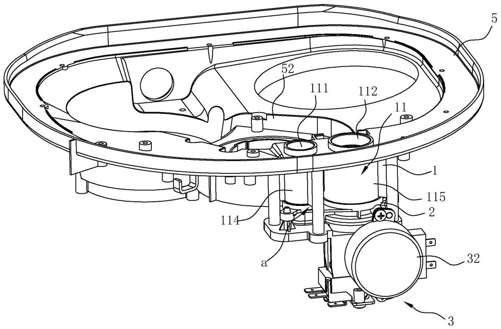
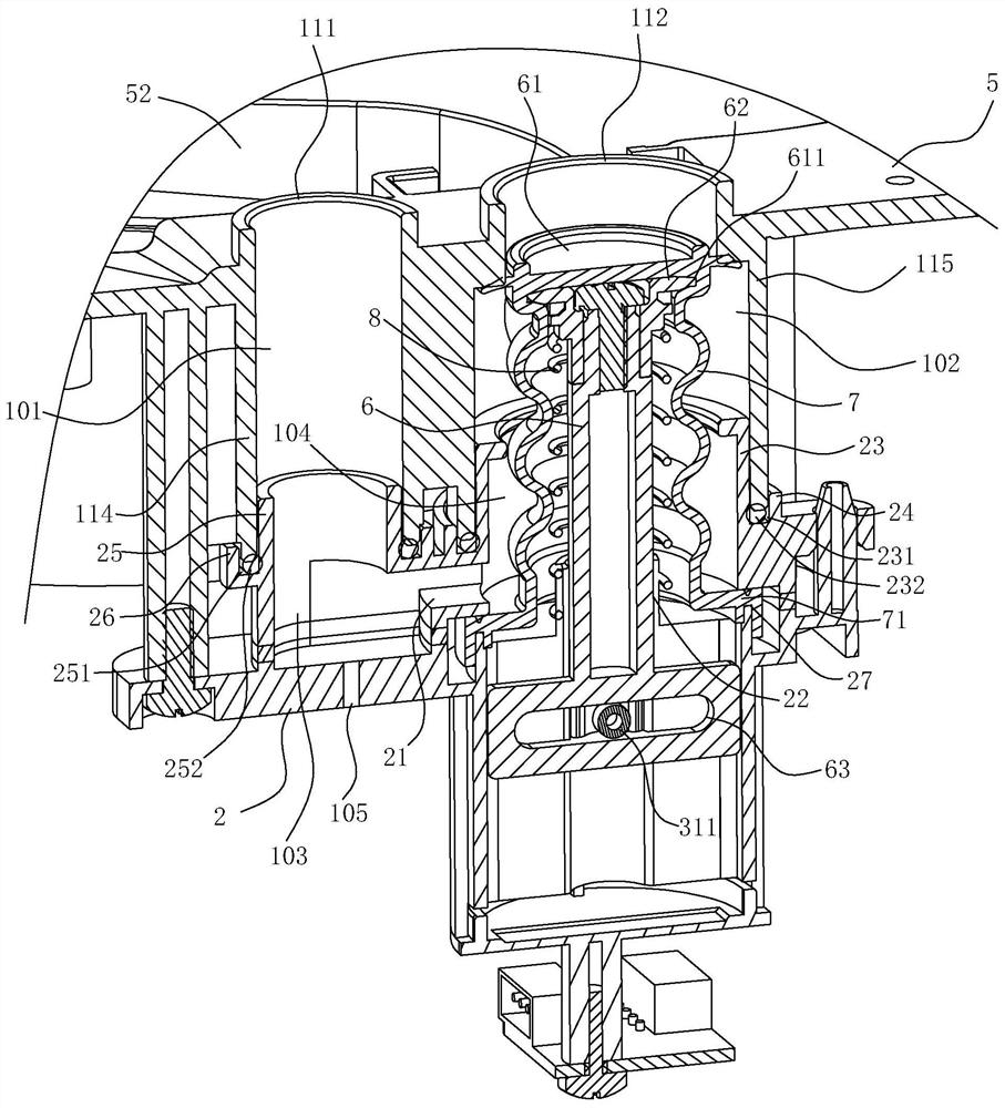
[0035] like Figures 1 to 6 As mentioned above, the water diverter valve in this embodiment includes a casing 1 , a fixed seat 2 , a movable column 6 , a driving component 3 and a control component 4 .

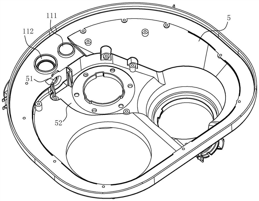
[0036] like figure 2 As shown, the above-mentioned housing 1 has a hollow water separation cavity 11, the side of the water separation cavity 11 has a water inlet 113 for docking with the water outlet 51 of the washing machine, and the top of the water separation cavity 11 has a first The water outlet 111 and the second water outlet 112 . The water separation cavity 11 is vertically arranged with a partition a that can divide it into a first cavity 101 corresponding to the first water outlet 111 and a second cavity 102 corresponding to the second water outlet 112, and the water inlet 113 corresponds to the second cavity 102. The cavity 102 ...


PUM


Abstract

The invention relates to a shunt valve and a cleaning machine applying the shunt valve, the shunt valve comprises a shell, a fixed seat, a movable column and a driving assembly, the shell is provided with a first water outlet and a second water outlet, and a partition plate capable of dividing a water diversion cavity into a first cavity corresponding to the first water outlet and a second cavity corresponding to the second water outlet is vertically arranged in the water diversion cavity; an opening capable of communicating the first cavity with the second cavity is formed in the bottom of the partition plate; the top of the movable column is provided with a sealing plug which can seal the second water outlet when the movable column ascends to the top of the second cavity and seal the opening when the movable column descends to the bottom of the second cavity. The water dividing cavity of the water dividing valve is in direct butt joint with the water outlet of the cleaning machine, and the sealing performance of the joint is improved; the first water outlet and the second water outlet are alternately opened and closed by the sealing plug through lifting of the movable column, independent and absolute sealing of the first water outlet and the second water outlet is achieved, the sealing performance and reliability in the water distribution state are improved, and the water distribution effect is improved advantageously.

Description

technical field [0001] The invention relates to a water separation valve and a washing machine using the water separation valve. Background technique [0002] For desktop and cabinet dishwashers, due to their large washing space, in order to achieve better washing results, three spray arms are generally designed with top, middle and lower spray arms; when working, the washing pump transports water to the top through pipes , middle and lower spray arms, the water is sprayed from the top, middle and lower spray arms and rinses the dishes and then falls back to the water cup at the bottom of the dishwasher, the washing pump sends the returned water to the top, middle and lower spray arms again , completes a cycle. Since there are many pipelines leading to each spray arm, if all the pipelines are opened, more water needs to be used to meet the needs of system circulation. [0003] In order to save water, the current dishwasher is generally designed with a water diverter valve....

Claims


Application Information

Patent Timeline
IPC IPC(8): F16K11/044F16K27/02F16K31/04F16K31/52A47L15/42
CPCF16K11/044F16K27/0263F16K31/047F16K31/52A47L15/4217
Inventor 张昌海晏建林丁权高旭东张健施郑赞
Owner NINGBO FOTILE KITCHEN WARE CO LTD
Why Eureka
Try Eureka