Double-acting electromagnetic actuator

An electromagnetic actuator and moving coil technology, applied in the direction of electromagnet, movable winding electromagnet, electromagnet with armature, etc., can solve the problem of response drop and achieve high reliability

Inactive Publication Date: 2004-07-28
SWEDISH CONRTOL SYST
View PDF2 Cites 3 Cited by
  • Summary
  • Abstract
  • Description
  • Claims
  • Application Information

AI Technical Summary

Problems solved by technology

This will cause a drop in response due to the considerable mass of the actuator and the need to overcome the force from the return spring

Method used


Image

  • Double-acting electromagnetic actuator
  • Double-acting electromagnetic actuator
  • Double-acting electromagnetic actuator

Examples


Embodiment Construction

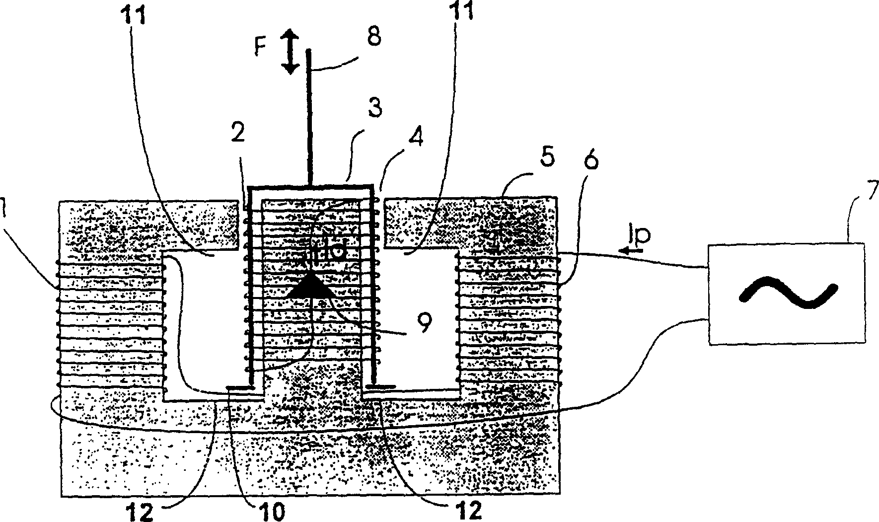
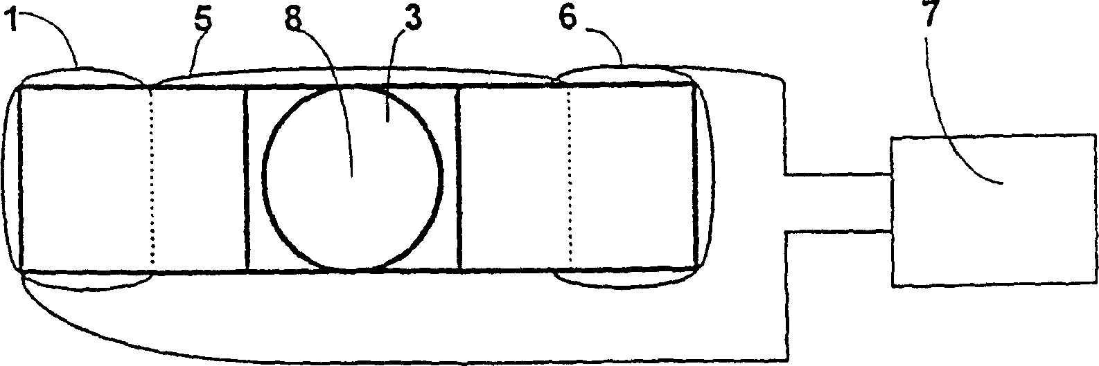
[0019] figure 1 An electromagnetic actuator of the present invention is shown. The stationary coils 1, 6 are wound on a core 5, preferably a ferrite core. In this embodiment, the stationary coil is divided into two serially connected coil segments, each coil being wound on one leg of a core layer having two parallel legs. In another embodiment, the core layer may be made of laminated sheet metal. But ferrite cores are preferable, although ferrite cores are more expensive.

[0020] A controllable power supply 7 is connected to the fixed coil to control the current I through the fixed coil P .

[0021] The coil 2 is movable relative to the fixed coil, and the coil 2 is wound on a coil former 3 . The coil template is preferably guided by a third leg of the core layer 5 which is juxtaposed with the leg on which the fixed coil is wound and which is located between these two legs.

[0022] The coil template with the coil wound on it is located in the air gap 4 between the two...


PUM


Abstract

The invention relates to an electromagnetic actuator for a rapid linear motion with a limited length of stroke. The electromagnetic actuator includes a stationary arranged first coil (1,6) and a second movable coil (2), with the winding of the stationary coil connected to controllable power source (7) and the winding of the movable coil is short-circuited without any galvanic connection to an external power source. The ends of the winding of the movable coil of the electromagnetic actuator is short-circuited via a rectifier element (9), preferably a diode. The diode allows a current to be developed in one direction only in the winding of the second coil, said current being induced from an electromagnetic field generated by a current through the first coil. In this manner is a double-acting electromagnetic actuator with very low weight obtained, resulting in very rapid response and high reliability, due to the lack of any external electrical connections to the movable coil.

Description

technical field [0001] The present invention relates to an electromagnetic actuator, and more particularly to an electromagnetic actuator with a moderate length of stroke having fast linear motion. Background technique [0002] It has long been known that coils are movable under the influence of a magnetic field. Examples of this can be found in loudspeakers with fixed permanent magnets, which have a movable voice coil encased in a magnetic field induced by the permanent magnets. The windings of the voice coil are connected to an external power source and, through current control, can give the coil the desired motion. The disadvantage of this solution is that the external connections are movable and subject to potential interruption. [0003] In United States patent US.A.5294850 a device is disclosed in which the electromagnetic field effect is capable of launching a missile. In this scheme fixed coils are used, capable of influencing coils placed ...

Claims


Application Information

Patent Timeline
Patent Type & Authority Patents(China)
IPC IPC(8): H01F7/16H01F7/06
CPCH01F7/066H01F7/06
Inventor 约翰·奥尔森
Owner SWEDISH CONRTOL SYST
Why Eureka
Try Eureka