Method and apparatus for rolling a tube

A kind of equipment and rough rolling technology, applied in the direction of metal rolling, metal rolling, metal rolling stand, etc., can solve the problem of high power of side roll rolling

Inactive Publication Date: 2007-08-01
库伯利集团有限公司
View PDF3 Cites 0 Cited by
  • Summary
  • Abstract
  • Description
  • Claims
  • Application Information

AI Technical Summary

Problems solved by technology

However, according to this method, the required rolling power of the side rolls is too high to achieve the required oval tube dimensions

Method used


Image

  • Method and apparatus for rolling a tube
  • Method and apparatus for rolling a tube

Examples


Embodiment Construction

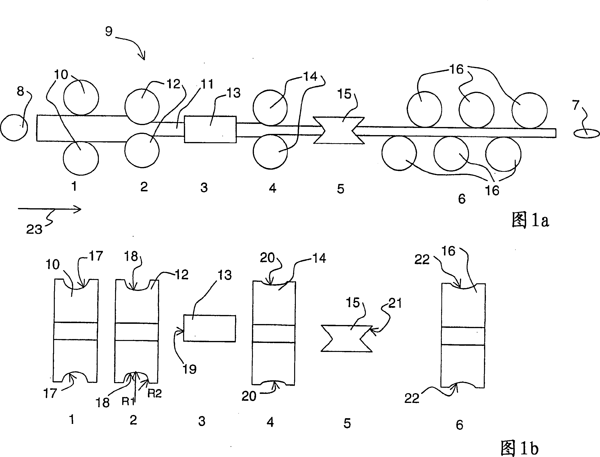
[0013] Figures 1a and 1b show the apparatus of the present invention for the manufacture of oval tubes. FIG. 1 b shows a cross-section of the roller shown in FIG. 1 a seen in the direction of arrow 23 . The cross section of the metal pipe is circular and made of hard or soft metal, such as copper pipe, the metal pipe enters the rolling equipment 9 in the conveying step 1, and the two conveying rollers 10 whose shape is consistent with the metal pipe 11 transfer the metal The tube is kept on a given straight line for the rolling operation. The conveying rollers can be positioned above and below the metal pipe, or on both sides thereof, and the surface 17 of the conveying roller in contact with the metal pipe has the same shape as the metal pipe. Conveyor rolls 10 convey the metal tube 11 to the roughing roll 2, where two roughing rolls 12 flatten the round metal tube, thereby changing the final dimensions of the tube. The roughing rolls 12 are located above and below the tube...


PUM


Abstract

The invention relates to a method for manufacturing ovalshaped metal tubes, where an essentially round-shaped metal tube is rolled both in the sideways direction and in the vertical direction of the tube, so that the metal tube (11) is rolled at least in two steps (2,4), and that between said rolling steps (2,4), the metal tube is rolled at least once in a direction that is perpendicular to the rolling direction of the rollng steps (2,4). In addition, the invention relates to an apparatus for manufacturing ovalshaped metal tubes.

Description

technical field [0001] The present invention relates to a method and an apparatus for manufacturing elliptical metal tubes by rolling. Background technique [0002] Elliptical tubes are used, for example, in gas heaters, where the advantage is that the outer surface area of ​​the tubes is increased relative to the amount of liquid contained in the tubes, and the circulation of the gas flame between the elliptical tubes is more favorable than that between circular tubes. In the prior art, the manufacture of the elliptical metal tube is to first process the plate into a U-shaped cross-section, and then weld and close the joint at one side of the above-mentioned shaped cross-section to form a tube. The manufacture of oval tubes can also be done by drawing the tube through an oval ring and by using molding techniques. When manufacturing oval tubes by rolling round tubes, it may happen that on one side of the tube, at the junction of the top and bottom rolls, a mark is left alon...

Claims


Application Information

Patent Timeline
Patent Type & Authority Patents(China)
IPC IPC(8): B21C37/15B21B13/00B21B13/06B21B15/00B21B17/14B21B31/16B21B31/18B21B31/30
CPCB21B2203/22B21B13/06B21C37/155B21B31/16B21B2273/22B21B13/005B21B2015/0071B21B17/14B21B31/30B21B31/18B21C37/15
Inventor T·瓦基帕塔
Owner 库伯利集团有限公司
Why Eureka
Try Eureka