Imaging method and device

An image and image-carrying technology, applied in the direction of electric recording process applying charge pattern, equipment for electric recording process applying charge pattern, electric recording technique, etc., can solve the problems such as lowering of fixing temperature, paper jam, and no consideration of the device, etc. Achieve the effect of preventing image shift, improving transportability, and good transferability

Inactive Publication Date: 2002-05-29
RICOH KK
View PDF3 Cites 14 Cited by
  • Summary
  • Abstract
  • Description
  • Claims
  • Application Information

AI Technical Summary

Problems solved by technology

[0010] However, in the above devices, it is sometimes necessary to use special paper
[0011] For example, in the case of special paper such as thick paper, if the image is formed as in the case of normal paper, it is difficult for the paper to pass through the conveying path, and paper bending, paper jams, or problems in image density or fixability may occur. Problems such as low image quality
For this problem, the devices described in the above-mentioned publications have not considered
[0012] In addition, when the intermediate transfer belt is used as the second image carrier and can be recorded on both sides, when special paper such as long recording paper is used, there is a problem of how to deal with long image data exceeding the circumference of the intermediate transfer belt.
[0013] In addition, when fixing long paper as special paper, there are problems such as lowering of the fixing temperature, correspondence between the paper feed unit and the paper discharge unit for long paper, and the simplification of the method of making the recording paper long paper into the information input device.
For the above-mentioned problem, the devices described in the above-mentioned publications do not involve

Method used


Image

  • Imaging method and device
  • Imaging method and device
  • Imaging method and device

Examples


Embodiment Construction

[0125] Embodiments of the present invention will be described in detail below with reference to the accompanying drawings.

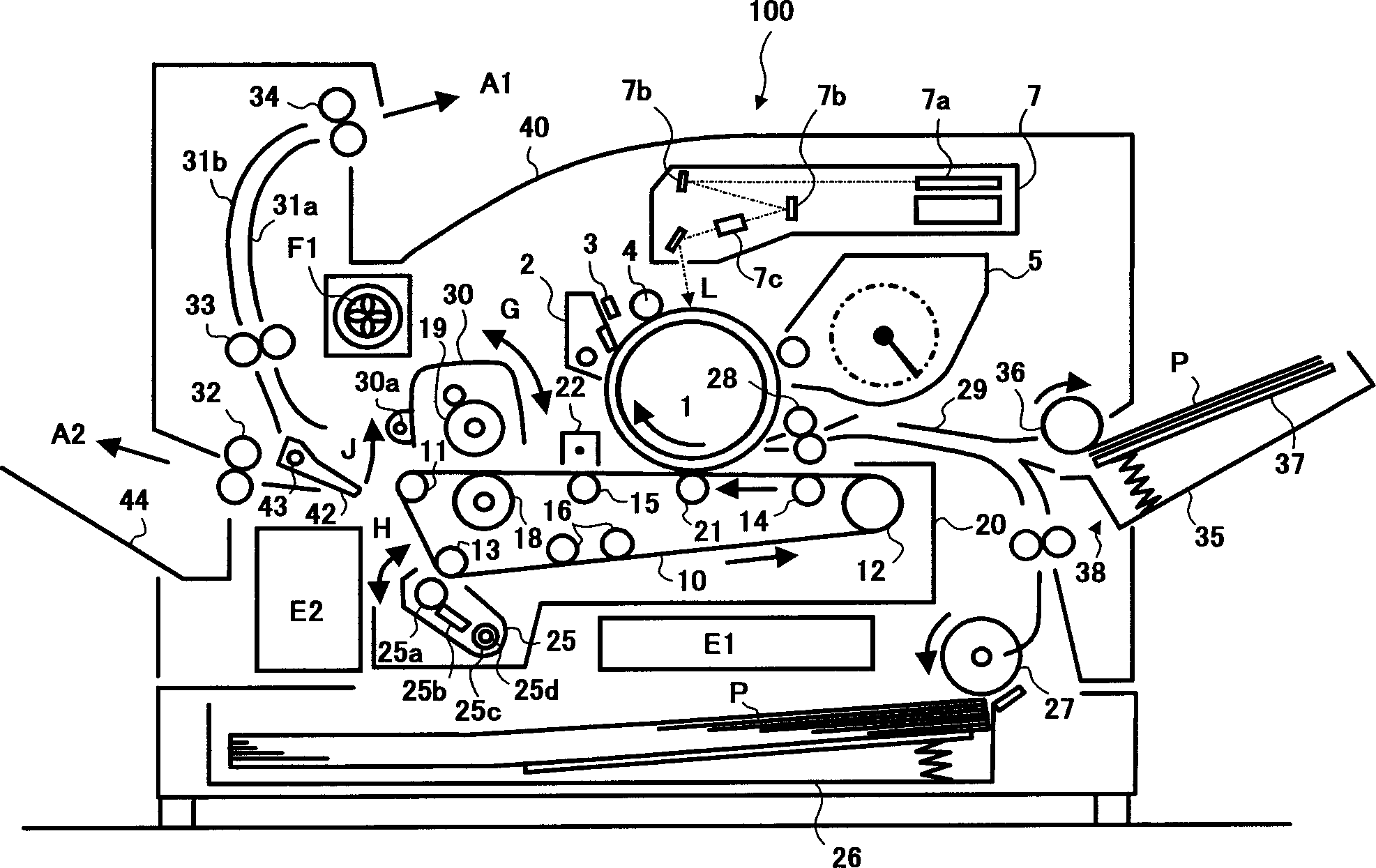
[0126] figure 1 It is a schematic sectional configuration diagram of a printer as an example of an image forming apparatus to which the present invention is applied.

[0127] In the printer 100 shown in the figure, a photoreceptor drum 1 serving as a first image carrier is disposed approximately in the center of the device. Around the photoreceptor drum 1, a cleaning device 2, a static elimination device 3, a charging device 4, and a developing device 5 are arranged. In the figure, an exposure device 7 is provided above the photoreceptor drum 1 , and laser light L emitted from the exposure device 7 is irradiated onto the photoreceptor 1 at a writing position between the charging device 4 and the developing device 5 .

[0128] In this embodiment, the photoreceptor drum 1, the cleaning device 2, the electricity removing device 3, the charging device 4, t...


PUM


Abstract

An image forming apparatus that is capable of forming an appropriate image even on a special transfer sheet, such as a thick and rigid transfer sheet (e.g., a cardboard and an envelope) and a long transfer sheet, etc. In the image forming apparatus, when the thick and rigid transfer sheet is used, a transfer bias applied to first and second transfer devices is increased by about 10 to 30% compared to that applied when a normal transfer sheet is used, and a temperature of fixing rollers is increased by about 10 to 30% compared to that when the normal transfer sheet is used. When the long transfer sheet that is longer than a circumferential length of a second image bearing member is used, an image transfer onto the second image bearing member is prohibited. In addition, the temperature of the fixing rollers is increased by about 10 to 30% compared to that when the normal transfer sheet is used.

Description

technical field [0001] The present invention relates to a method and apparatus for forming images on both sides of a recording medium. Background technique [0002] Some image forming apparatuses such as copiers, printers, and facsimiles can form images on both sides of a recording medium (hereinafter simply referred to as “paper” for simplicity). In the conventional image forming apparatus capable of double-sided recording, the following method is generally used: the image (developed image) formed on one side of the image carrier is transferred to paper, fixed, and then the paper is turned over by a reversing passage or the like. , the paper is fed again, and the image on the other side (developed image) is transferred to the back of the paper for fixing. [0003] In the case of recording on both sides as described above, there are many problems in ensuring the reliability of paper transportation due to the switching of the paper transportation direc...

Claims


Application Information

Patent Timeline
Patent Type & Authority Applications(China)
IPC IPC(8): G03G15/00G03G15/20G03G15/23G03G21/16
CPCG03G15/0131G03G2215/0119G03G2221/1678G03G2215/1695G03G15/20G03G15/6552G03G2215/00447G03G2215/0129G03G15/0178G03G2215/0132G03G2215/00016G03G15/0194
Inventor 持丸英明小俣安国
Owner RICOH KK
Why Eureka
Try Eureka