Centrifugal vacuum cleaner

A vacuum cleaner and centrifugal technology, applied in suction filters and other directions, can solve problems such as damage to the motor, increase noise, damage to the suction generator, etc., to prevent damage, reduce noise, and prevent interference.

Inactive Publication Date: 2004-02-11
LG ELECTRONICS (TIANJIN) APPLIANCES CO LTD
View PDF0 Cites 4 Cited by
  • Summary
  • Abstract
  • Description
  • Claims
  • Application Information

AI Technical Summary

Problems solved by technology

Especially the dust discharged from the exhaust pipe will flow into the suction generator and damage the suction generator
[0009] Therefore, because the entire air flow path is too long, it will cause pressure loss, which not only increases the noise, but also increases the motor load of the suction generator, resulting in damage to the motor
That is, due to the arrangement of the discharge pipe of the centrifugal compressor, the air flow path between the suction generator and the fuselage is too long, resulting in pressure loss

Method used


Image

  • Centrifugal vacuum cleaner
  • Centrifugal vacuum cleaner
  • Centrifugal vacuum cleaner

Examples


Embodiment Construction

[0026] The centrifugal vacuum cleaner of the present invention will be described in further detail below in conjunction with the accompanying drawings and specific embodiments:

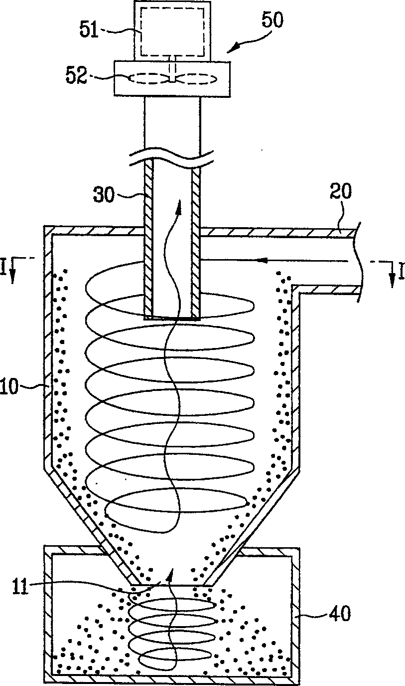
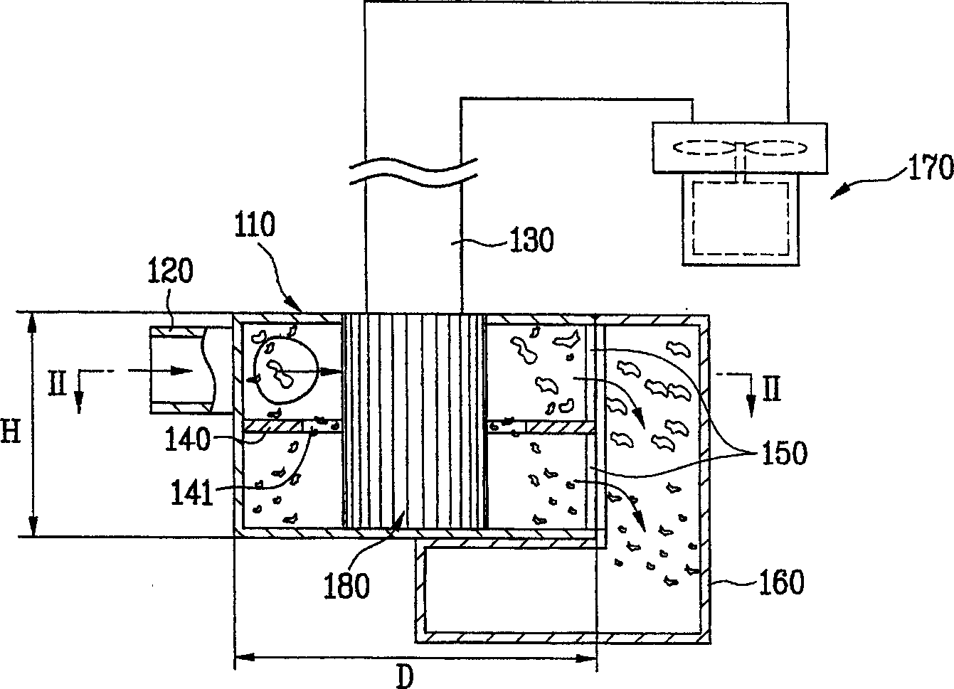
[0027] like Figure 3 to Figure 5 As shown, the centrifugal vacuum cleaner designed by the present invention includes a body 110 , a suction pipe 120 , an exhaust pipe 130 , a partition 140 , a sewage hole 150 and a dust collection cylinder 160 . The overall shape of the body 110 is cylindrical, and its height H is smaller than or equal to the diameter D. However, not limited thereto, the height H of the fuselage 110 may be greater than the diameter D of the fuselage 110 .

[0028] The suction pipe 120 runs through the outer end of the fuselage 110 and is connected with the fuselage. More specifically, the suction duct 120 is connected to the periphery of the fuselage 110 in a tangential direction.

[0029] The function of the exhaust pipe 130 is to discharge the outside air flowing into the inside...


PUM


Abstract

The centrifugal vacuum cleaner includes one body; one air sucking pipe on one side of and connected to the peripheral of the body to suck outer air and garbage; one exhaust pipe connected to one of the top side and the bottom side and to exhaust air from the body; one dust collecting barrel to collect garbage from the garbage exhausting holes; and at least one portioning board inside the body to separate the inside space into several communicated parts. The centrifugal vacuum cleaner has low noise and can well collect various kinds of garbage.

Description

technical field [0001] The invention relates to a vacuum cleaner, in particular to a centrifugal vacuum cleaner which uses the centrifugal principle to collect garbage. Background technique [0002] Generally, the centrifugal vacuum cleaner uses the centrifugal principle to separate the air that rotates with the garbage and discharge it to the outside, and only collects the garbage. [0003] like figure 1 , 2 The prior art centrifugal cleaner shown comprises: a conical body 10, a suction pipe 20 connected to the suction channel of the vacuum cleaner, an exhaust pipe 30 for discharging air flowing into the inside of the body, and a collection and air The dust collection tube 40 of the separated garbage. The suction pipe 20 is connected to the upper peripheral end of the fuselage 10 . The exhaust pipe 30 runs through the top of the fuselage 10 and extends into the upper side of the fuselage 10, and the other end of the exhaust pipe 30 is connected to a suction generator 50...

Claims


Application Information

Patent Timeline
Patent Type & Authority Applications(China)
IPC IPC(8): A47L9/16
Inventor 林庆锡郑景善柳廷玩李成华
Owner LG ELECTRONICS (TIANJIN) APPLIANCES CO LTD
Why Eureka
Try Eureka