
Cyclone duster

A technology of cyclone dust collector and cyclone, which is applied in the direction of swirl devices and devices whose axial direction of swirl can be reversed, etc., which can solve the problems of increasing the motor load of the suction generator, damaging the suction generator, and long flow path , to achieve the effect of reducing load, reducing pressure loss and reducing contact time

Inactive Publication Date: 2004-11-24
LG ELECTRONICS (TIANJIN) APPLIANCES CO LTD
View PDF0 Cites 3 Cited by
  • Summary
  • Abstract
  • Description
  • Claims
  • Application Information

AI Technical Summary

Problems solved by technology

At this time, the dust and garbage output through the exhaust pipe will flow into the suction generator, thereby damaging the suction generator
[0011] 3rd, because the entire flow path of the air is too long, there is a pressure loss, which not only increases the noise, but also increases the load of the motor in the suction generator
Cause dust or other dirt to flow into the cyclone body again

Method used


Image

  • Cyclone duster
  • Cyclone duster
  • Cyclone duster

Examples


Embodiment Construction

[0033] The cyclone dust collector of the present invention will be further described in detail below in conjunction with the accompanying drawings and specific embodiments:

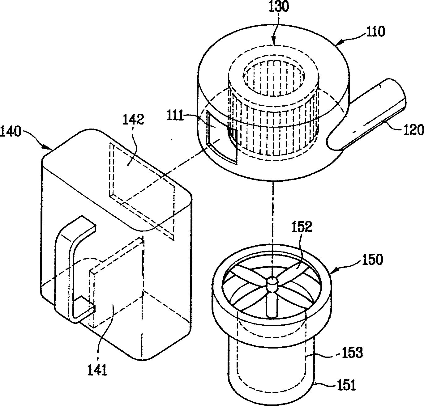
[0034] Such as image 3 , 4 , 5, the cyclone dust collector designed by the present invention includes a cyclone body 110, a dirt separator 110, a dust collector 140, and is directly connected to the cyclone body 110 and directly connected to the dirt separator 130 The suction generator 150 above constitutes.

[0035] The cyclone body 110 constituting the cyclone dust collector adopts a cylindrical structure with a width (diameter) equal to or greater than the height, and is connected with a suction pipe 120 for sucking in outside air, and is also provided with a sewage hole 111 for discharging dirt.

[0036] The suction pipe 120 is connected to the cyclone body 110 in the tangential direction of the outer surface of the cyclone body 110, and the suction pipe 120 and the sewage hole 111 are arranged on ...


PUM


Abstract

The cyclone duster includes cyclone body connected to sucking pipe for sucking in air from outside, pollutant separator inside the cyclone body to separate pollutant form the sucked air, sucking force generator connected directly to the cyclone body or the pollutant separator to generate sucking force, and dust collector to collect exhausted from the cyclone body. The present invention has shortened path, reasonable configuration, minimized pressure loss and high dust collecting efficiency.

Description

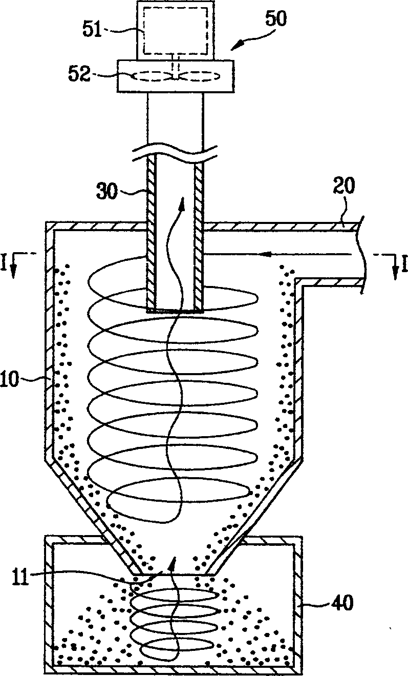
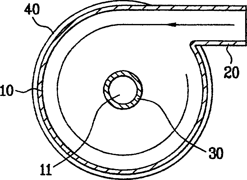
technical field [0001] The invention relates to a dust collector, in particular to a cyclone dust collector which utilizes the principle of a cyclone to collect dirt. Background technique [0002] Usually, the cyclone dust collector uses the principle of the cyclone to separate the garbage and dust from the high-speed airflow, collect them, and discharge the air to the outside. [0003] Such as figure 1 , 2 As shown, the existing cyclone dust collector generally includes: a conical cyclone body 10, a suction pipe 20 for sucking in external air, an exhaust pipe 30 for discharging the air inside the cyclone body and collecting air from the cyclone body. A dust collector 40 for separated dust and rubbish is formed. The suction pipe 20 is connected to the upper end of the periphery of the cyclone body 10 . The exhaust pipe 30 penetrates from the top of the cyclone body 10 to the upper end inside the cyclone body 10 , and is thus connected to the body. The other end of the e...

Claims


Application Information

Patent Timeline
Patent Type & Authority Applications(China)
IPC IPC(8): B04C5/08
Inventor 柳俊相林庆锡郑景善柳廷玩
Owner LG ELECTRONICS (TIANJIN) APPLIANCES CO LTD
Learn More