Telephone receiver

A receiver and partition technology, applied in the field of receivers, can solve the problems of low product qualification rate and insufficient installation position.

Pending Publication Date: 2017-05-31
SUZHOU YICHUAN TECH CO LTD
View PDF3 Cites 2 Cited by
  • Summary
  • Abstract
  • Description
  • Claims
  • Application Information

AI Technical Summary

Problems solved by technology

[0006] Therefore, the technical problem to be solved by the present invention is to overcome the problem that the installation position of each

Method used


Image

  • Telephone receiver
  • Telephone receiver
  • Telephone receiver

Examples


Embodiment 1

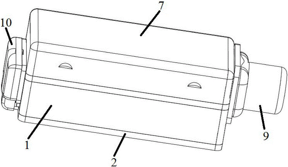
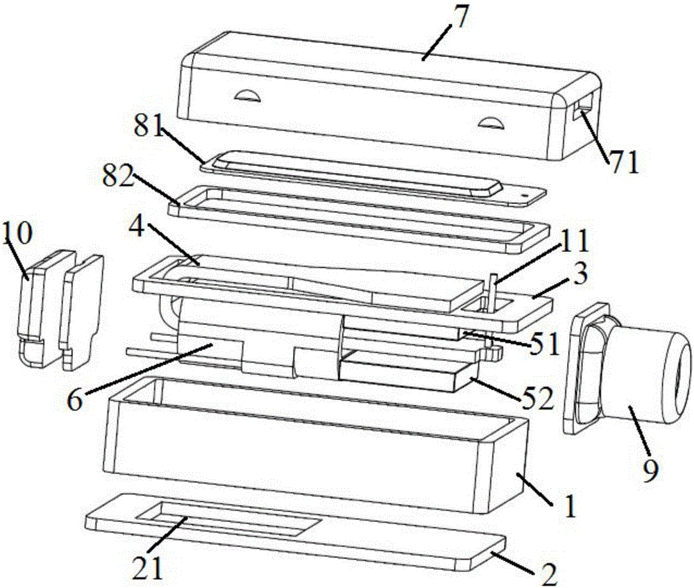
[0049] This embodiment provides a receiver, such as figure 1 with figure 2 As shown, it includes an upper shell 7, a diaphragm mechanism 8, a lower shell, a partition 3, a connecting piece 11 and an electromagnetic drive mechanism.

[0050] Such as figure 1 As shown, the upper case 7 has a first connection opening, the diaphragm mechanism 8 is fixed in the upper case 7 , and a sound port 71 is opened on the side wall of the upper case 7 . The lower shell is composed of a middle shell 1 and a base 2, the middle shell 1 has a second connection port corresponding to the first connection port, and an opening opposite to the second connection opening; the middle shell 1 is preferably a hollow cuboid, or a cube , or a cylinder. The partition plate 3 is clamped and fixed between the first connection opening and the second connection opening, and the base 2 can be sealed and assembled on the opening of the middle shell 1, so that an upper cavity is formed between the partition pla...


PUM


Abstract

The invention discloses a telephone receiver which comprises an upper shell, a lower shell, a separating plate and an electromagnetic driving mechanism, wherein the lower shell is composed of a middle shell and a base; the separating plate is arranged in an inner cavity formed by buckling the upper shell and the lower shell; a coil, a first magnet and a reed of the electromagnetic driving mechanism are fixed on the separating plate, a cantilever of the reed passes through the coil, crosses the first magnet and is connected with one end of a connecting piece, and the other end of the connecting piece passes through the separating plate and is connected with a vibrating diaphragm mechanism; a second magnet of the electromagnetic driving mechanism is fixed on the base and is dead against the first magnet; and the end faces, closed to the coil, of the two magnets are respectively in contact with the end face of the coil. When the telephone receiver is assembled, the vibrating diaphragm mechanism and the upper shell form a first module; the second magnet and the base form a second module; the coil, the reed, the first magnet and the separating plate form a third module; and only the end face of the second magnet needs to be aligned with the end face of the coil, which is taken as a locating basis, the base is fixed on an opening of the middle shell, the first magnet is dead against the second magnet, and thus alignment is easy in an assembling process of the telephone receiver.

Description

technical field [0001] The invention relates to the technical field of sound emitting devices, in particular to a receiver. Background technique [0002] The receiver is widely used in portable electronic equipment such as mobile phones, computers, hearing aids, etc., and is a tiny device for sound generation. During the production and manufacture of this micro-miniature device, it is the goal pursued by many manufacturers to improve the sound output power of the receiver while simplifying the manufacturing process. [0003] For example, the Chinese patent document CN205232410U discloses a receiver, which includes a lower shell, an upper shell, and a diaphragm arranged between the upper shell and the lower shell. A diaphragm mechanism is arranged in the inner cavity of the upper shell. An electromagnetic driving mechanism is arranged in the enclosed cavity, and the electromagnetic driving mechanism includes a reed fixed on the partition plate and a magnet at one end, the ot...

Claims


Application Information

Patent Timeline
IPC IPC(8): H04R1/08H04R1/02H04R31/00
CPCH04R1/02H04R1/08H04R31/006H04R2201/029
Inventor 吴哲胡牧
Owner SUZHOU YICHUAN TECH CO LTD
Why Eureka
Try Eureka