Link up device of push boat/lighter

A connecting device and barge technology, which is applied to ship components, ship construction, towing/push equipment, etc., can solve problems such as mutual impact, difficult emergency disengagement, maneuverability and course stability, speed limit, etc., and achieve the goal of reducing installation requirements Effect

Inactive Publication Date: 2007-04-18
WUHAN GUOYU LOGISTICS IND GROUP
View PDF0 Cites 5 Cited by
  • Summary
  • Abstract
  • Description
  • Claims
  • Application Information

AI Technical Summary

Problems solved by technology

This connection method is greatly affected by sea conditions. There is mutual impact between the push boat and the barge, and the maneuverability, course stability, and speed are all limited, and it is difficult to disengage in an emergency.

Method used


Image

  • Link up device of push boat/lighter
  • Link up device of push boat/lighter
  • Link up device of push boat/lighter

Examples


Embodiment Construction

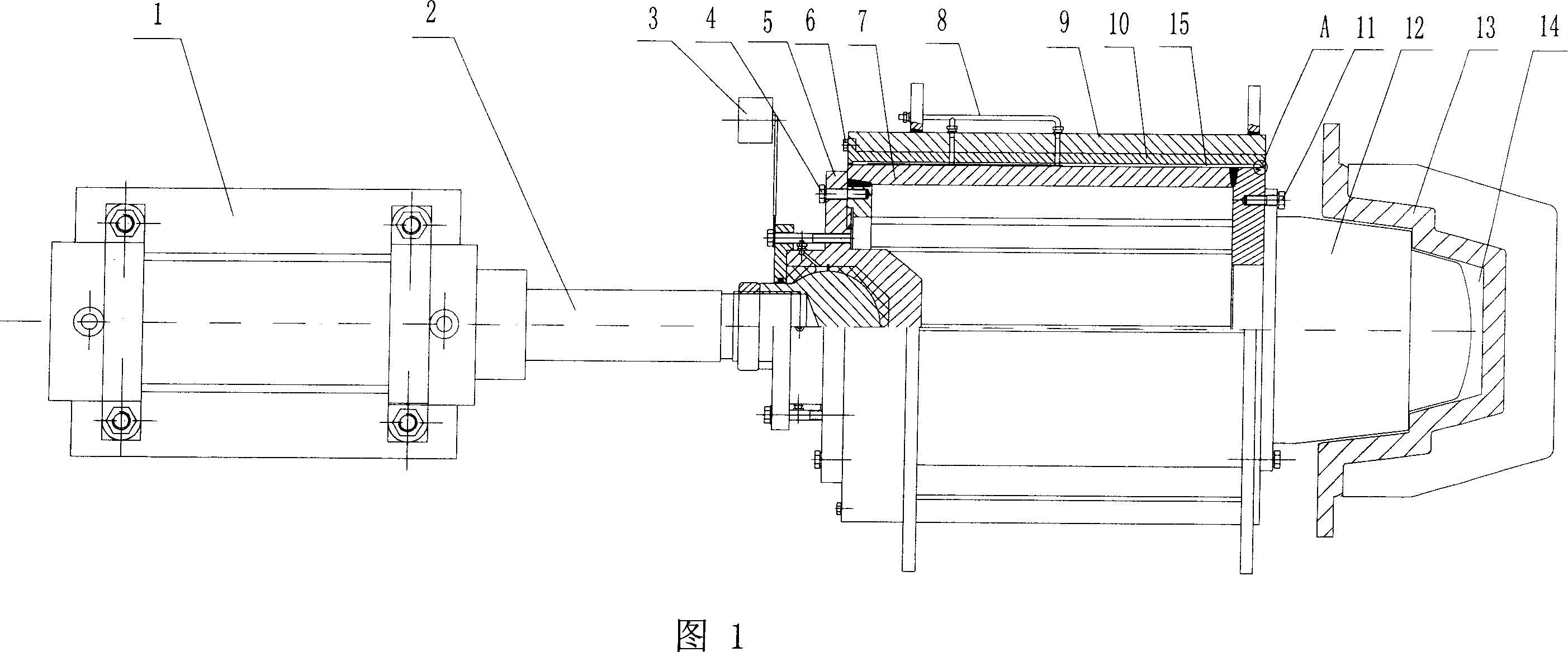
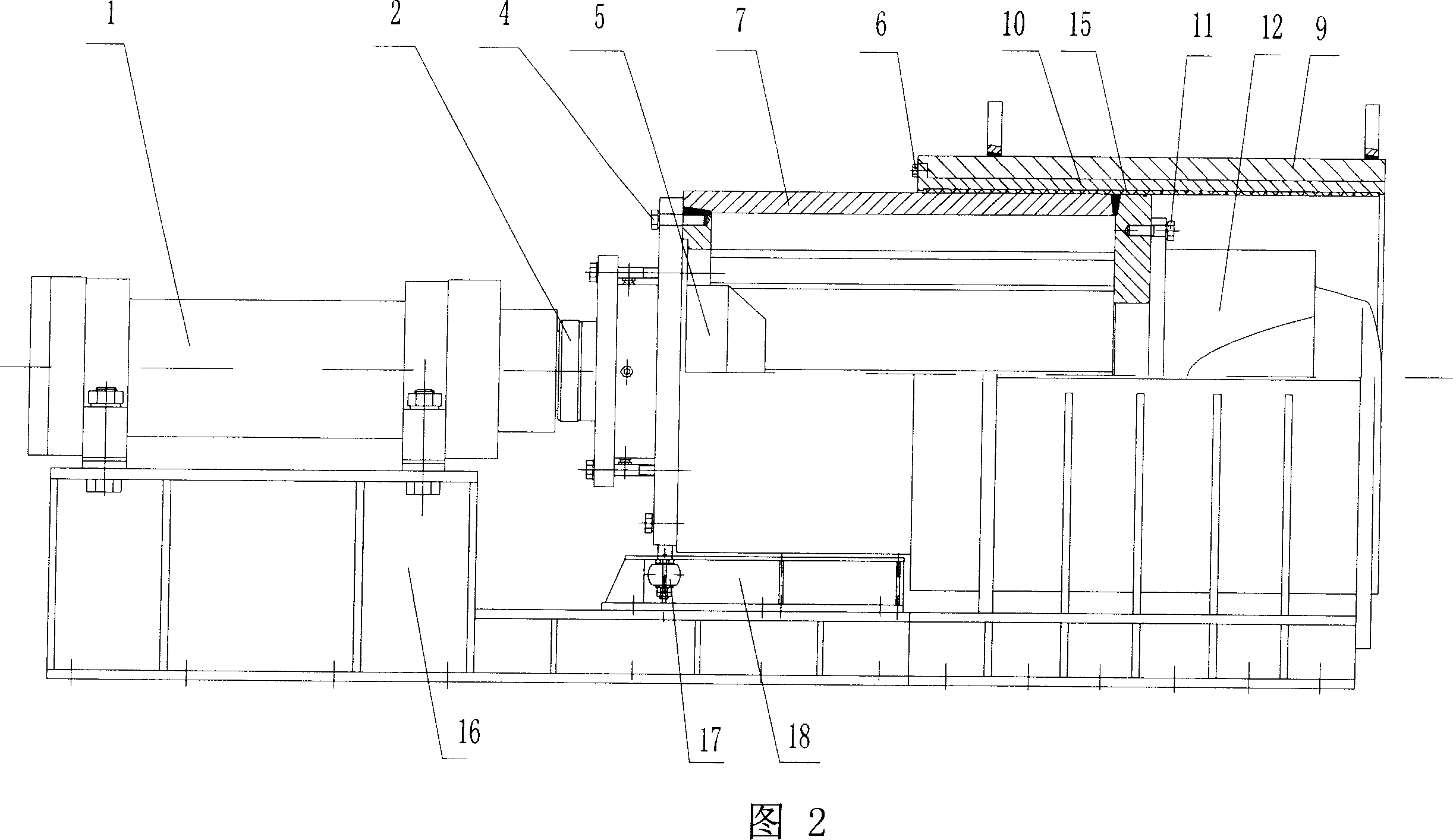
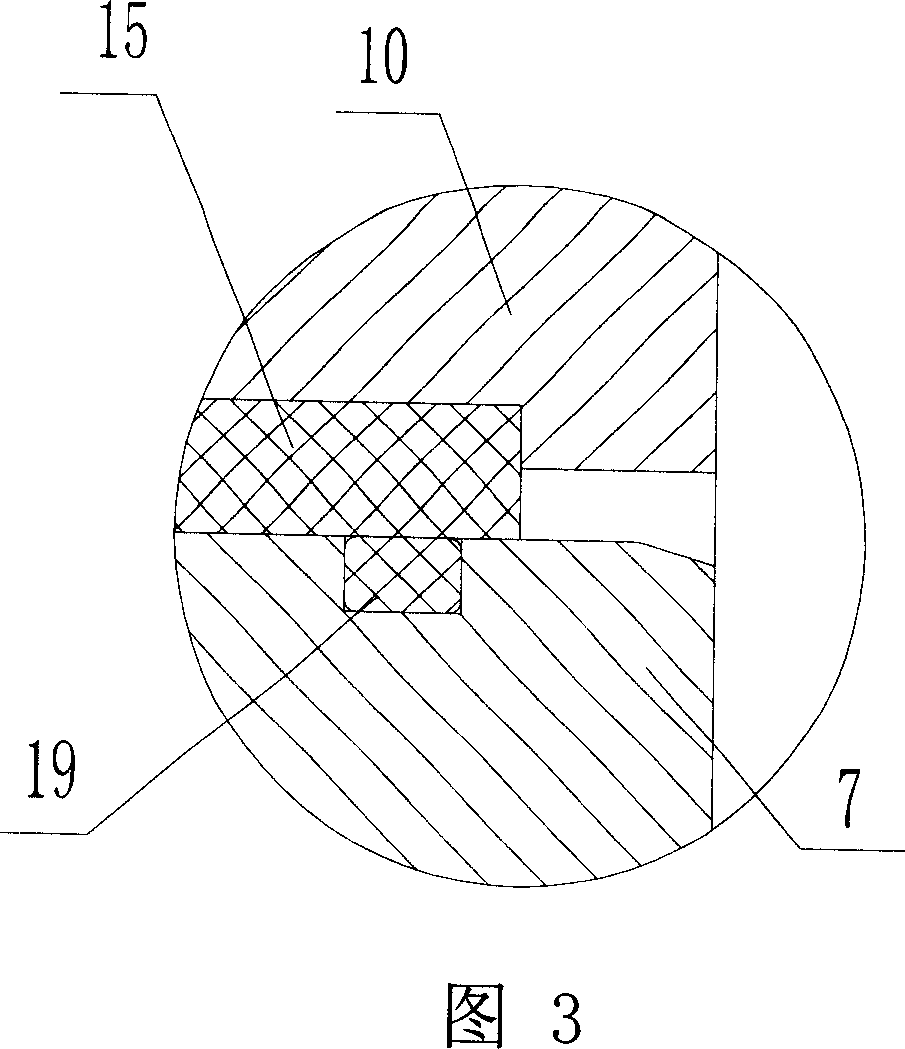
[0032] As shown in Fig. 1, Fig. 2, Fig. 7, Fig. 8, Fig. 9, Fig. 10, Fig. 15, Fig. 16, Fig. 17 and Fig. 18, the pusher / barge coupling device includes a hydraulic cylinder 1 and a thrust bearing 5 , pin body 7, housing 9, sliding bearing sleeve 10, pin head 12, pin hole slideway plate 13, first engineering plastic alloy material MGA layer 15, common base 16, the piston rod 2 of hydraulic cylinder 1 is supported by thrust bearing 5 is hinged with the left side of the pin body 7, and the pin body 7 is a hollow cylinder, and the hydraulic cylinder 1 is fixedly connected with the left part of the common base 16 (by bolts); the housing 9 is fixedly connected with the right part of the common base 16 (Fixed connection or welding by bolts), the housing 9 is a cylindrical cavity 26, the sliding bearing sleeve 10 is located in the cylindrical cavity 26 of the housing 9 and is fixedly connected with the housing 9 by the second bolt 6, the sliding bearing The cover 10 is provided with a fi...


PUM


Abstract

A coupling mechanism between a push ship and a barge is composed of a hydraulic cylinder with piston and piston rod, a thrust bearing, a pin body, a casing, a slide bearing sleeve with an engineering plastic-alloy layer on its inner surface, a pin head fixed to said pin body, a plate with pin hole and slide way and fixed to the tail of barge, and a common base.

Description

technical field [0001] The invention relates to a coupling device between a push boat and a barge. Background technique [0002] Most of the coupling devices between the pusher boats and barges navigating in rivers and seas are hoisting and side tying and towing. Suspension and towing: The tugboat and the barge are flexibly connected by a steel wire rope and a cable. The maneuverability and course stability of the barge are difficult to control, and the speed is also limited. Sideside tying and towing: A fastening method in which the barge leans against the side of the tugboat and uses a wire rope to tie short cables. It is often used for short-distance coastal transportation or port operations. This connection method is greatly affected by sea conditions. There is mutual impact between the push boat and the barge, the maneuverability, course stability, and speed are all limited, and it is difficult to disengage in an emergency. Contents of the invention [0003] The obj...

Claims


Application Information

Patent Timeline
Patent Type & Authority Applications(China)
IPC IPC(8): B63B21/56B63B35/70
Inventor 王卫和
Owner WUHAN GUOYU LOGISTICS IND GROUP
Why Eureka
Try Eureka