
Gasket type measuring hole and pressure type flow control device using the measuring hole

A technology of flow measuring hole and flow measuring orifice plate, which is applied in the direction of flow control, measuring device, non-electric variable control, etc., can solve the problem of not being able to realize space saving, and achieve good sealing effect

Inactive Publication Date: 2011-11-30
FUJIKIN INC
View PDF5 Cites 6 Cited by
  • Summary
  • Abstract
  • Description
  • Claims
  • Application Information

AI Technical Summary

Problems solved by technology

[0012] In the case of using the washer-type orifice in the above-mentioned pressure type flow control device, two washer-type orifices 29, 30 having different flow characteristics must be respectively provided in the two fluid passages 26b, 26b formed in parallel. The problem of not being able to realize space saving

Method used


Image

  • Gasket type measuring hole and pressure type flow control device using the measuring hole
  • Gasket type measuring hole and pressure type flow control device using the measuring hole
  • Gasket type measuring hole and pressure type flow control device using the measuring hole

Examples


Embodiment Construction

[0076] Hereinafter, embodiments of the present invention will be described in detail based on the drawings.

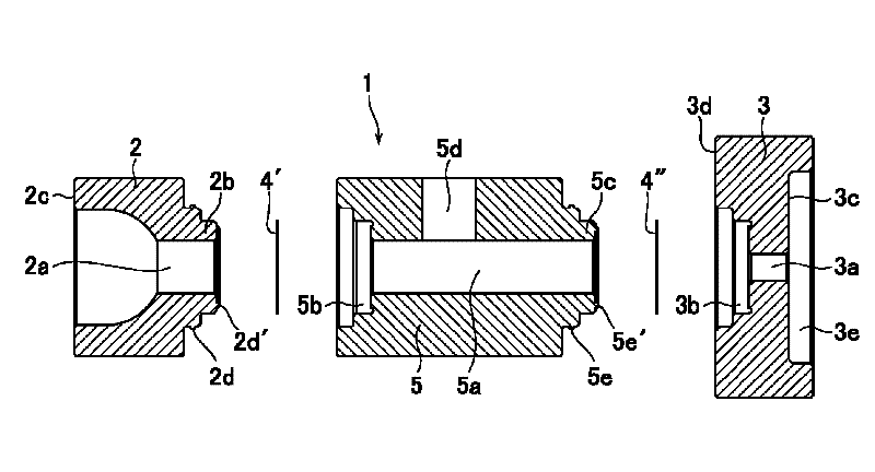
[0077] Figure 1 to Figure 4 A gasket-type flow hole 1 and a pressure-type flow control device using the flow hole according to an embodiment of the present invention are shown.

[0078] The above-mentioned gasket type flow hole 1 such as figure 1 and figure 2 As shown, the convex flow hole base 2 has a through-shaped passage 2a in the center and a protrusion 2b for fitting on the inner end surface, has a through-shaped passage 3a in the center, and has a fitting on the inner end surface. Combining the concave flow measuring hole base 3 of the concave portion 3b and the flow measuring orifice plate 4 formed with a flow measuring orifice (not shown) in the center, the convex flow measuring hole base 2 and the concave shape The flow measuring hole base 3 is combined, the flow measuring orifice plate 4 is airtightly inserted between the two measuring flow hole bases ...


PUM


Abstract

Provided are a gasket-type orifice having excellent sealing properties and occupying a reduced space, and a pressure-type flow rate control device using the gasket-type orifice. A gasket-type orifice (1) comprising: an orifice base (2) having a through path (2a) at the center thereof; an orifice base (3) having at the center thereof a through path (3a) communicating with the path (2a) of the orifice base (2); and an orifice plate (4) air-tightly inserted between the orifice bases (2, 3) and having an orifice hole at the center thereof. The gasket-type orifice is adapted to be provided in a fluid path, and the outer end surfaces of both the orifice bases (2, 3) are made to serve as seal surfaces (2c, 3c). Among both the orifice bases (2, 3), the orifice base (3) located on the downstream side is made to have an outer diameter greater than the outer diameter of the orifice base (2) located on the upstream side. The outer peripheral edge portion of the inner end surface of the orifice base (3) located on the downstream side is made to serve as a seal surface (3d).

Description

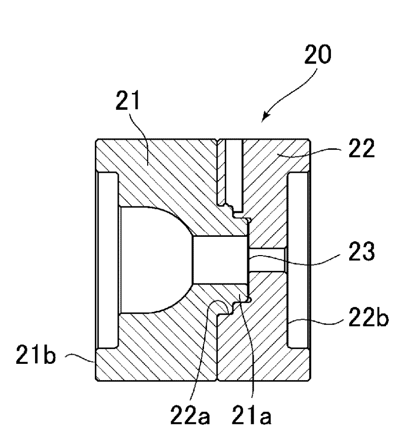
technical field [0001] The present invention relates to a gasket-type flow measuring hole used in a pressure type flow control device for controlling the flow of fluid, which is interposed in a fluid supply line of semiconductor manufacturing equipment, chemical industry equipment, pharmaceutical industry equipment, food industry equipment, etc. The pressure-type flow control device for the flow hole is specially designed with a gasket-type flow hole that has good sealing performance and can save space, and the pressure-type flow control device using the flow hole. Background technique [0002] Conventionally, as such a gasket-type flow hole and a pressure-type flow control device using the flow hole, for example, a structure disclosed in JP-A-2007-057474 (see Patent Document 1) is known. [0003] That is, the above-mentioned gasket type flow hole 20 is as Figure 19 As shown, the flow hole base 21 provided with the protruding portion 21a for fitting is combined with the flo...

Claims


Application Information

Patent Timeline
Patent Type & Authority Applications(China)
IPC IPC(8): F15D1/02F16L55/00G01F1/00G01F1/42
CPCF15D1/025G01F1/42G01F1/40F16L23/20G05D7/0635F15D1/02F16L55/00G01F1/00
Inventor 广濑隆筱原努吉田俊英执行耕平山路道雄
Owner FUJIKIN INC
Learn More