

Electrolytic capacitor
An electrolytic capacitor and electrical connection technology, applied in the direction of electrolytic capacitors, capacitors, capacitor terminals, etc., can solve the problems of productivity inhibition, reduction of electrolytic capacitor characteristics, and ESL increase, and achieve the effect of ESL reduction.
- Summary
- Abstract
- Description
- Claims
- Application Information
AI Technical Summary
Problems solved by technology
Method used
Image

Examples
no. 1 approach
[0117] Here, an electrolytic capacitor using a double-sided crimp terminal as the first anode (cathode) lead terminal and a single-side crimp terminal as the second anode (cathode) lead terminal will be described.
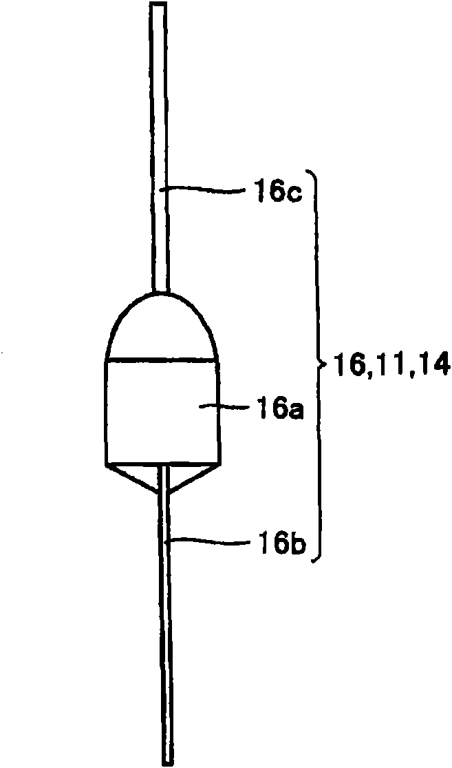
[0118] like figure 1 As shown, the double-sided crimping terminal 16 is formed into a roughly bilaterally symmetrical shape with respect to the lead wire 16c by two identical molds, and a cylindrical boss portion 16a and a plate-shaped connection to the anode (cathode) foil are formed. part 16b and a cylindrical lead 16c serving as an anode (cathode) terminal. The lead wire 16c is provided on one end side of the boss part 16a, and the connection part 16b is provided on the other end side of the boss part 16a. It should be noted that, in figure 1 In , the plate-shaped connecting portion 16b is arranged in a direction perpendicular to the paper surface.
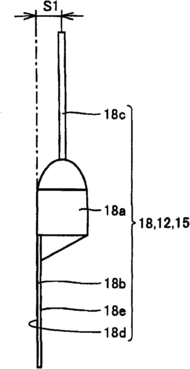
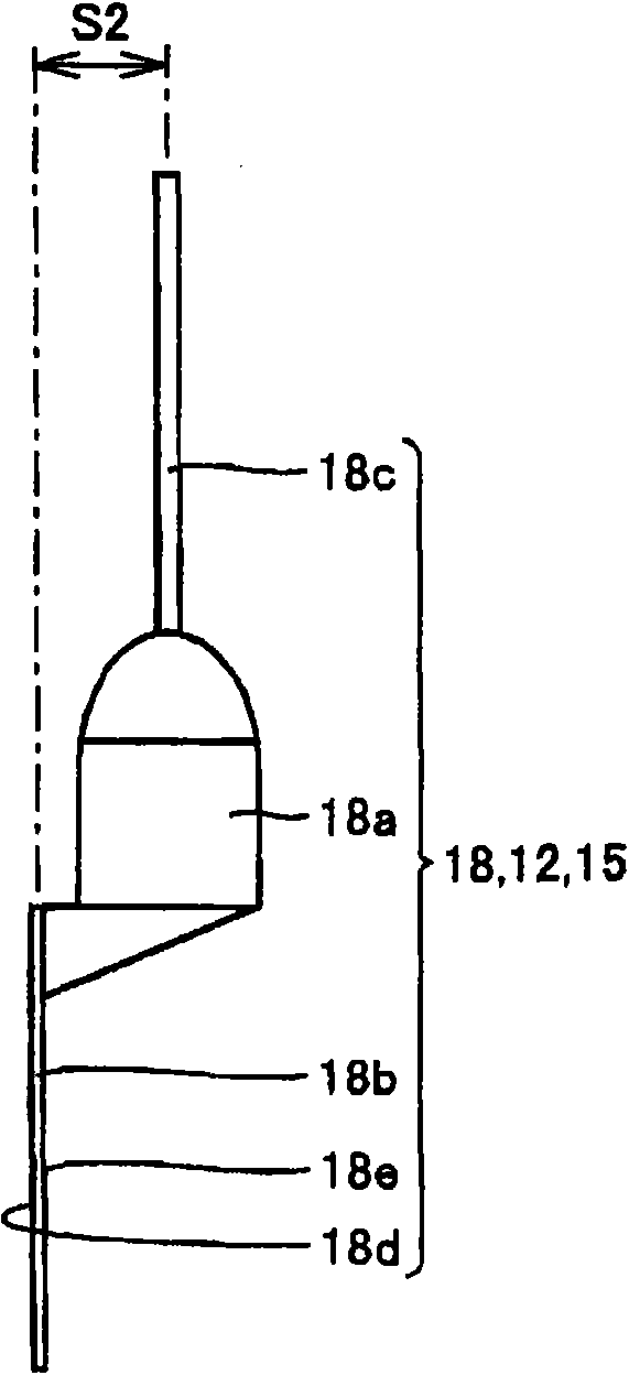
[0119] On the other hand, if Figure 2A and 2B As shown, the single-side crimping terminal 18 is formed in...
no. 2 approach
[0139] Here, an electrolytic capacitor using a one-sided crimp terminal as the first anode (cathode) lead terminal and a double-side crimp terminal as the second anode (cathode) lead terminal will be described.
[0140] First, if Figure 13As shown, a one-side crimping terminal 18 is connected as a first anode lead protruding terminal 11 and a double-side crimping terminal 16 is connected as a second anode lead protruding terminal 12 at a predetermined position in the longitudinal direction of the anode foil 3 . In addition, a one-sided crimp terminal 18 is connected as a first cathode lead protrusion terminal 14 and a double-side crimp terminal 16 is connected as a second cathode lead protrusion terminal 15 at a predetermined position in the longitudinal direction of the cathode foil 4 .
[0141] At this time, like the above-mentioned electrolytic capacitor, the first anode lead terminal 11 is arranged in a predetermined first circumferential direction in a coiled state with ...
Embodiment 1
[0167] The inventor produced an electrolytic capacitor using a double-sided crimp terminal as the first anode (cathode) lead terminal and a single-side crimp terminal as the second anode (cathode) lead terminal (first embodiment) , and an electrolytic capacitor (second embodiment) using a single-sided crimping terminal as the first anode (cathode) lead terminal and using a double-sided crimping terminal as the second anode (cathode) lead terminal (second embodiment) One, the position (arrangement shape) of the four anode (cathode) lead protruding terminals (leads) after completion was evaluated.
[0168] It should be noted that the specific manufacturing method of the electrolytic capacitor is as described in the above-mentioned first embodiment and second embodiment, and the diameter is 8.0 mm. In addition, as Comparative Example 1, 500 electrolytic capacitors using double-sided crimping terminals as the first (two) anode (cathode) lead protruding terminals were produced, and...
PUM
 Abstract
Description
Claims
Application Information