Switchgear

A switching device and switching contact technology, applied in the direction of electrical switches, polarized relays, contacts, etc., can solve the problems of not easy to reliably cut off arc current, low reliability of switching characteristics, etc. Effect

Inactive Publication Date: 2004-03-10
ORMON CORP
View PDF1 Cites 1 Cited by
  • Summary
  • Abstract
  • Description
  • Claims
  • Application Information

AI Technical Summary

Problems solved by technology

As a result, it is not easy to cut off the generated arc current reliably, and there is a problem that the reliability of switching characteristics is low.

Method used


Image

  • Switchgear
  • Switchgear
  • Switchgear

Examples


Embodiment Construction

[0036] according to Figure 1 to Figure 15 The accompanying drawings illustrate embodiments to which the invention relates.

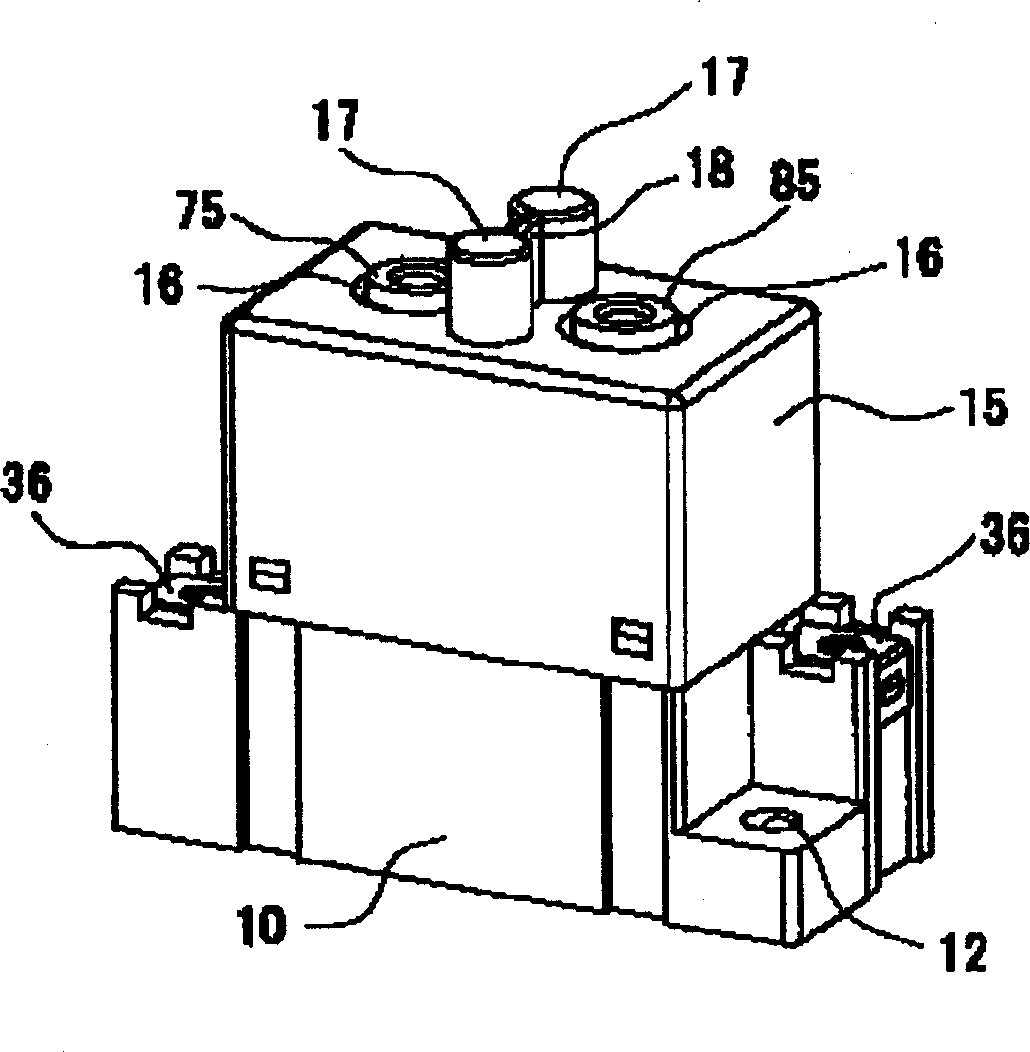
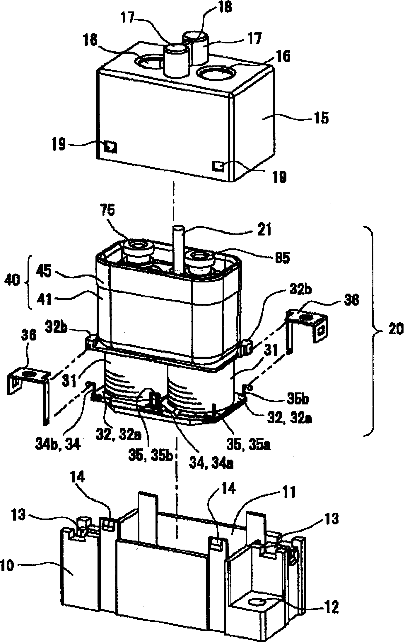
[0037] The first embodiment that the present invention relates to is applicable to the situation of the relay for DC load switching, such as figure 1 as well as figure 2 As shown, the relay body 20 is accommodated in the space divided by the integrated box-shaped casing 10 and the box-shaped cover 15 .

[0038] Such as figure 2 As shown, the above-mentioned box-shaped casing 10 has a concave portion 11 that can accommodate the electromagnet block 30 described later, and a pair of plane corners positioned on the diagonal line are provided with through holes 12 for fixing. A connection recess 13 is provided at the corner of the plane, and a connection nut (not shown) is embedded in the connection recess 13 .

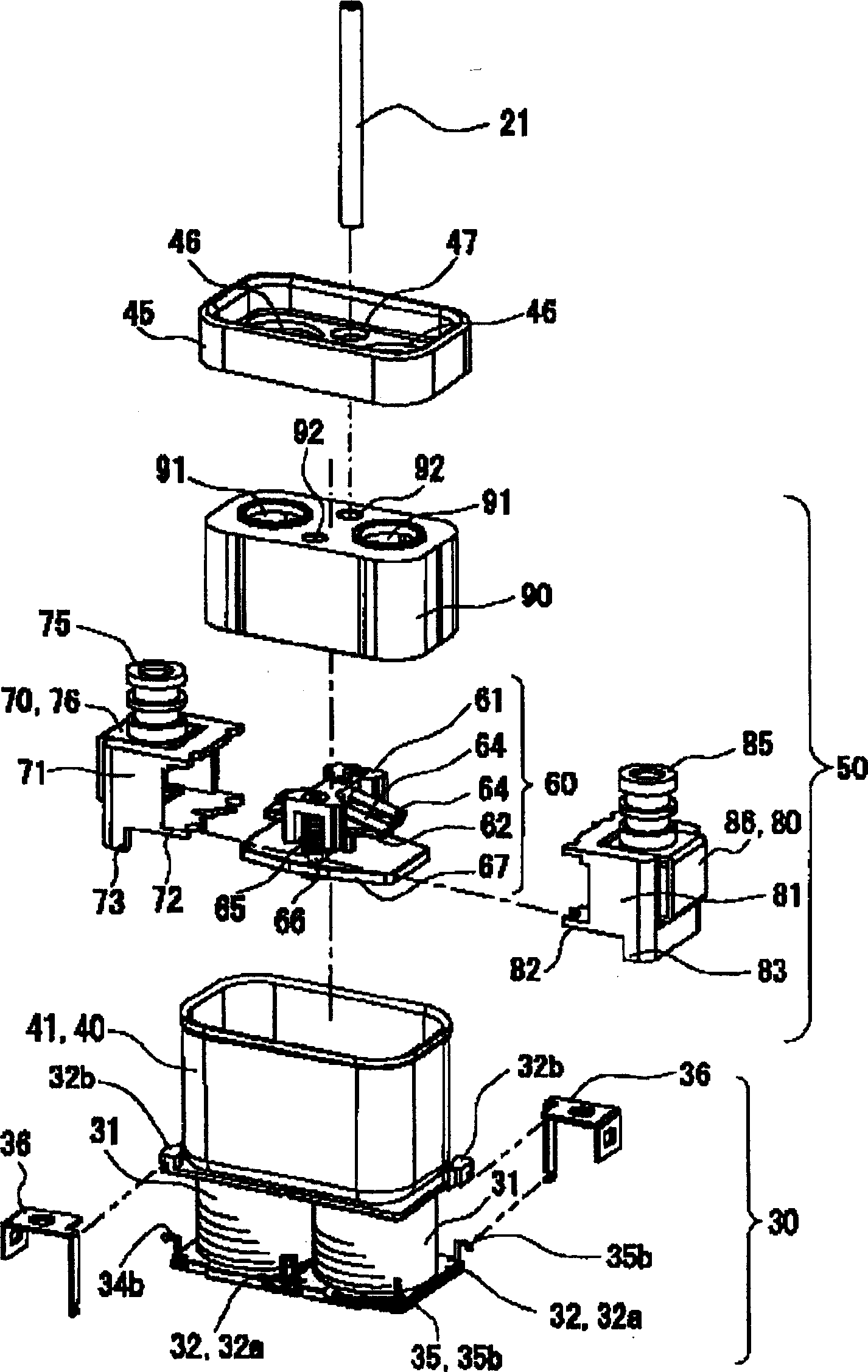
[0039] The box-shaped cover 15 can be fitted into the box-shaped casing 10 and has a shape capable of housing a sealed casing block 40 descri...


PUM


Abstract

A switching device which can be small-sized by improving a shielding performance and can improve the reliability of switching characteristics. A permanent magnet disposed near stationary contacts is arranged in its pole-face perpendicularly of the axis of a moving contact member.

Description

technical field [0001] The invention relates to a switch device, in particular to an electromagnetic relay, a switch, a timer and other switch devices for switching current. Background technique [0002] As a conventional switching device for cutting off direct current, for example, a sealed relay device disclosed in Japanese Patent Application Laid-Open No. 9-510040. [0003] That is, through the excitation and demagnetization of the coil portion 40, the plunger 9 contacts or disengages from the core center portion 4, and the sliding movement of the armature component 8 and the armature shaft 10 integrated with the plunger 9 in the axial direction can be achieved. The movable contact plate 21 is in contact with or separated from the fixed contacts 22 , 22 . [0004] In the above-mentioned sealed relay device, the magnetic force of the permanent magnet 33 installed inside the fixed node 22 attracts outward and cuts off the arc current generated when the movable contact plat...

Claims


Application Information

Patent Timeline
Patent Type & Authority Applications(China)
IPC IPC(8): H01H9/44H01H1/66H01H50/00H01H50/38H01H50/54H01H51/22
CPCH01H9/443H01H2009/305H01H1/2025H01H50/546H01H2050/025H01H51/2209
Inventor 西田刚桝井保幸前西钢三
Owner ORMON CORP
Why Eureka
Try Eureka