AC plasma display panel

A display panel, plasma technology, applied in alternating current plasma display panels, tube structural parts, maintenance/scanning electrodes, etc., can solve the problems such as the decline of the pass rate, the influence of the display quality of the plasma display, and the interference of the display unit.

Inactive Publication Date: 2005-01-12
AU OPTRONICS CORP
View PDF1 Cites 0 Cited by
  • Summary
  • Abstract
  • Description
  • Claims
  • Application Information

AI Technical Summary

Problems solved by technology

[0008] However, the range of the existing barrier wall 28 structure that can accept ultraviolet radiation is only the left and right side walls, so its luminous brightness is limited; in addition, the traditional elongated barrier wall 28 design is easy to generate ionized gas cross talk of discharge To the phenomenon of adjacent light-emitting regions 162, this will form the interference between the display units (cells), and then affect the display quality of the plasma display 10
[0009] U.S. Patent No. 6376987 discloses a new type of electrode design for an AC plasma display panel, which utilizes a discharge electrode (row electrode) with a continuous body portion at the position of the discharge gap (discharge gap) to avoid the discharge electrode The independent projecting portion (projecting portion) changes the discharge characteristics due to position errors, and can improve the shortcomings of the low discharge efficiency of the traditional linear discharge electrode
However, if an open circuit occurs in the design of the independent discharge electrode, point defects will be generated, resulting in a decline in the pass rate, and the independent discharge electrode requires high alignment accuracy, which may easily cause changes in the discharge characteristics. However, a discharge electrode with a continuous body portion will cause adjacent sub-pixel regions to interact with each other, thereby reducing the operating voltage range.

Method used


Image

  • AC plasma display panel
  • AC plasma display panel
  • AC plasma display panel

Examples


no. 1 example

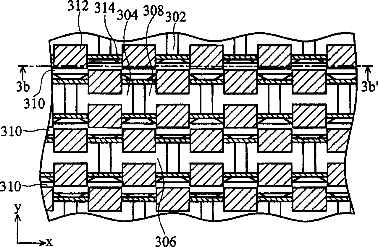
[0070] Please also refer to Figure 3A and Figure 3B , Figure 3A A plan view showing the structure of barrier ribs and electrodes according to the first embodiment of the present invention, Figure 3B show Figure 3A Sectional view along 3b-3b'.

[0071] A plurality of barrier ribs 302 are arranged on the back plate 382 in a triangular pixel arrangement, and are divided into a plurality of sub-pixel regions. The sub-pixel regions can be polygonal or circular, and in this preferred embodiment, they are hexagonal shape. The rear plate 382 is preferably a glass substrate. In a preferred embodiment of the present invention, the triangular pixels are arranged in accordance with the three primary colors , and the hexagonal barrier ribs are arranged in a triangular form to form R discharge space 304, G discharge space 306, and B discharge Space 308, and its barrier wall 384 is preferably divided into two colors, upper and lower layers. The upper layer is black to increase the...

no. 2 example

[0077] Please also refer to Figure 9 and Figure 8 , Figure 9 A plan view showing the structure of barrier ribs and electrodes according to the second embodiment of the present invention, Figure 8 show the invention Figure 9 Sectional view along 8-8'.

[0078] A plurality of hexagonal barrier ribs 902 are arranged in a triangular pixel arrangement on the rear panel 800, and the rear panel 800 is preferably a glass substrate. In a preferred embodiment of the present invention, the triangular pixels are arranged in accordance with the three primary colors , and the hexagonal barrier ribs are arranged in a triangle to form R discharge space 904, G discharge space 906, and B discharge. Space 908, and its barrier wall 902 is preferably divided into two colors, upper and lower layers. The upper layer is black to increase the contrast of the picture, while the lower layer is white to reflect visible light to increase the brightness of the picture. The preferred height of the ...

no. 3 example

[0082] Such as Figure 11 As shown, a plurality of hexagonal barrier ribs 452 are arranged in a triangular pixel arrangement on the rear panel, and the rear panel is preferably a glass substrate. In a preferred embodiment of the present invention, the triangular pixels are arranged in accordance with the three primary colors , and the hexagonal barrier ribs are arranged in a triangle to form R discharge space 454, G discharge space 456, and B discharge. Space 458, and its barrier wall 452 is preferably divided into two colors, upper and lower layers. The upper layer is black to increase the contrast of the picture, while the lower layer is white to reflect visible light to increase the brightness of the picture. The preferred height of the barrier wall 452 is 100 μm to 180 μm.

[0083] In addition, a plurality of auxiliary electrodes 460 are disposed on the upper glass substrate to form a zigzag shape that changes with the shape of the barrier ribs. In this preferred embodim...


PUM


Abstract

Structure of faceplate includes a back plate, multiple auxiliary pixel areas, a front plate, and multiple maintain poles. Multiple closed interclude wall areas separate multiple auxiliary pixel areas arranged on the back plate in triangular arrangement mode of pixel. Multiple maintain poles including multiple auxiliary poles and multiple extension poles are setup at surface of the front plate faced to back plate. The extension poles are extended along first direction and parallel to each other. Discharging gap is formed in auxiliary pixel area between extended poles from auxiliary poles and adjacent extended poles from maintain poles. There is at least one relevant connection pole to connect each extended pole to adjacent extended pole.

Description

technical field [0001] The invention relates to an AC plasma display panel, in particular to a structure of a discharge electrode and a barrier wall of an AC plasma display panel. Background technique [0002] A plasma display (Plasma Display Panel, referred to as PDP) is a thin display, and its main feature is that it can be a super-sized, ultra-thin screen to save a lot of screen space. The light emitting principle of the plasma display is similar to that of a fluorescent lamp. Inert gas is injected into the vacuum glass tank, and the inert gas is pressurized by voltage to generate a plasma effect and emit ultraviolet rays. At this time, the ultraviolet rays are irradiated on the glass tank wall surface. Fluorescent material, which can make the fluorescent material excite red, green or blue visible light. In this way, the screen of a plasma display is composed of hundreds of thousands of units that can emit light by themselves, and each light-emitting unit contains small ...

Claims


Application Information

Patent Timeline
Patent Type & Authority Applications(China)
IPC IPC(8): H01J11/10H01J11/24
Inventor 苏耀庆
Owner AU OPTRONICS CORP
Why Eureka
Try Eureka