Gas-liquid separator

A technology of gas-liquid separator and separation chamber, which is applied in the field of gas-phase and liquid-phase separators, and can solve the problems of unstable internal swirling airflow, improved separation effect of mixed gas-liquid flow, and large space volume.

Inactive Publication Date: 2006-04-26
CHINA UNIV OF PETROLEUM (BEIJING)
View PDF0 Cites 8 Cited by
  • Summary
  • Abstract
  • Description
  • Claims
  • Application Information

AI Technical Summary

Problems solved by technology

The disadvantage of this equipment is that the internal swirling air flow is unstable, and the separation effect of the re-separated mixed gas-liquid flow needs to be improved
In particular, since the circulation pipe is placed outside the separation chamber, the space occupied by the equipment is too large

Method used


Image

  • Gas-liquid separator
  • Gas-liquid separator
  • Gas-liquid separator

Examples


Embodiment Construction

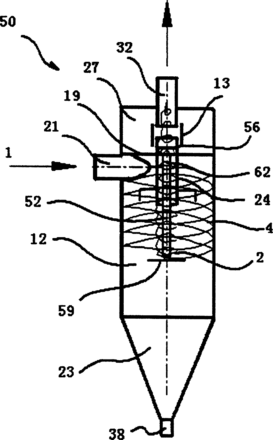
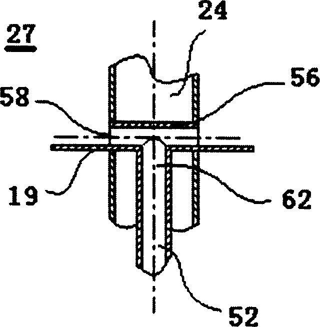
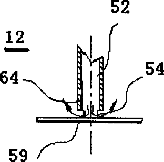
[0015] Refer to attached figure 1 , a kind of gas-liquid separator 50 that the present invention provides, it comprises separation chamber 12, is provided with the inlet 21 of mixed gas-liquid flow 1 on separation chamber 12, and one end of separation chamber 12 has separation chamber 27 again, in separation chamber 12 A partition 19 is provided between the re-separation chamber 27 . The chimneys 24 respectively extend toward both sides of the partition plate 19 . One end 26 of the gas riser 24 is located in the separation chamber 12 , the other end 25 is located in the re-separation chamber 27 and is opposite to the end 31 of the exhaust pipe 32 , and the other end of the separation chamber 12 has a liquid collection chamber 23 . The circulation pipe 52 is located inside the separation chamber 12, and the longitudinal axis of the circulation pipe 52 extends in the same direction as the longitudinal axis of the separation chamber 12. A part of the circulation pipe 52 extends...


PUM


Abstract

This invention provides a liquor-air separator (50), which comprises a separating chamber (12) whose one end is connected with the reseparating chamber (27), and a baffle (19) between the separating chamber (12) and the reseparating chamber (27); one end of the raising air tube (24) is inside the separating chamber (12), while the other end (25) is in the reseparating chamber (27) corresponding to the end (31) of the discharging pipe(32); the other end of the separating chamber (12) has a liquor collecting chamber (23). The circulation pipe (52) is inside the separating chamber (12), and the longitudinal axis of the circulation pipe (52) is along the same way with the longitudinal axis of the separating chamber (12); one part of the circulation pipe (52) is extended to the inside of the raise air pipe (24), between the outer wall of the circulation pipe and the inner wall of the raise air pipe it has a circular gap; one end (62) of the circulation pipe (52) is connected with the horizontal pipe (56), and the horizontal pipe (56) is connected with the reseparating chamber (27).

Description

technical field [0001] The invention relates to a gas-liquid separator, which is especially suitable for rotating air flow to separate gas phase matter and liquid phase matter in a mixed gas-liquid flow. Background technique [0002] In the production process of petrochemical products, with the continuous improvement and perfection of the existing technology, the gas-liquid separation technology has been greatly developed. In the existing technology, such as Figure 4 The gas-liquid separation equipment shown, the working principle of this separation equipment is roughly the same as that of a cyclone separator for separating gas and solid. During the operation of this separation device, the mixed gas-liquid flow 1 enters the separation chamber 12 through the inlet 21 arranged along the tangential direction, and the mixed gas-liquid flow 1 entering the separation chamber 12 rotates and moves in the separation chamber 12, and the rotating mixed gas The liquid flow 1 rotates do...

Claims


Application Information

Patent Timeline
Patent Type & Authority Applications(China)
IPC IPC(8): B04C5/00B01D45/16B01D53/26
Inventor 孙国刚
Owner CHINA UNIV OF PETROLEUM (BEIJING)
Why Eureka
Try Eureka