Optical sheet, backlight, and liquid crystal display device

一种光学片材、元件的技术,应用在照明和加热设备、光学、光学元件等方向,能够解决偏振光分离特性恶化、增强液晶面板侧亮度、外观模糊等问题

Active Publication Date: 2007-04-11
SONY CORP
View PDF1 Cites 8 Cited by
  • Summary
  • Abstract
  • Description
  • Claims
  • Application Information

AI Technical Summary

Problems solved by technology

The second-order transmitted light component T2 is the luminous flux component emitted to the wide-angle side outside the effective angle field of view of the liquid crystal panel, and does not contribute to the enhancement of brightness
[0009] In addition, depending on the angle-dependent characteristics of the polarized light separation sheet arranged on the subsequent stage, polarized light separation characteristics are sometimes extremely deteriorated due to the directionality of incident light, which becomes an obstacle to effectively enhance the brightness of the liquid crystal panel side
[0010] In addition, in the case where the above-mentioned prism sheet is interposed between the diffusion sheet and the liquid crystal panel, blurred appearance occurs

Method used


Image

  • Optical sheet, backlight, and liquid crystal display device
  • Optical sheet, backlight, and liquid crystal display device
  • Optical sheet, backlight, and liquid crystal display device

Examples


example 1

[0178] (Wherein, R=3, K=-2, A=10 -5 , B, C, ... = 0)

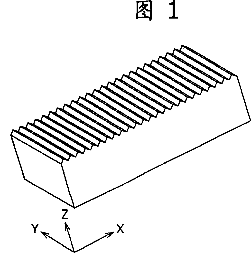
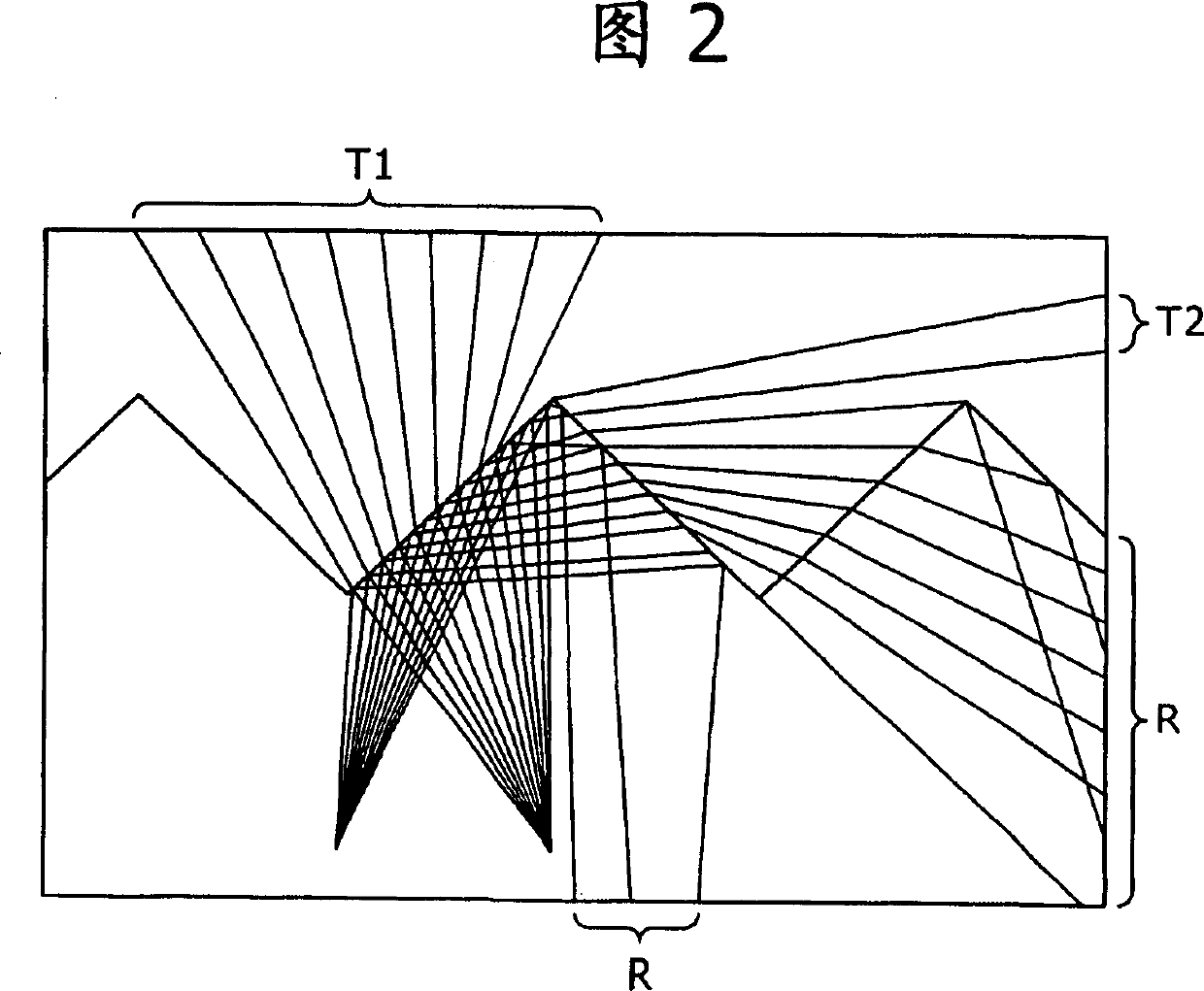
[0179] FIG. 9 shows a part of the XZ cross section of the lens sheet of Working Example 1 on an enlarged scale. A large number of cylindrical lens elements having a finite focal length on the emission side of illumination light and having bilaterally symmetrical high-order aspheric surfaces are successively arranged on the lens sheet. The aspherical cross-sectional shape is obtained by satisfying the expression (1) Z = X 2 / ( 3 + ( 9 + X 2 ) ) + 10 - 5 X 4 express.

[0180] Next, with reference to FIG. 9 , the action and effect ...

example 2

[0192] (where R=5, K=-10, A=5×10 -5 , B, C, ... = 0)

[0193] FIG. 11 shows a part of the XZ cross section of the lens sheet of Working Example 2 on an enlarged scale. On the lens sheet are successively arranged cylindrical lens elements having a finite focal length on the emission side of the illumination light and having left-right symmetrical high-order aspheric surfaces. The shape of the aspheric surface is determined by satisfying the expression (1) Z = X 2 / ( 5 + ( 25 + 9 X 2 ) ) + 5 × 10 - 5 X 4 express.

[0194]...

example 3

[0199] (wherein, R=1, K=-2, A=10 -5 , B, C, ... = 0)

[0200] FIG. 13 shows a part of the XZ cross section of the lens sheet of Working Example 3 on an enlarged scale. On the lens sheet are successively arranged cylindrical lens elements having a finite focal length on the emission side of the illumination light and having left-right symmetrical high-order aspheric surfaces. The shape of the aspheric surface is determined by satisfying the expression (1) Z = X 2 / ( 1 + ( 1 + X 2 ) ) + 10 - 5 X 4 express.

[0201] Next, with reference to FIG. 13 , the action and effect of the lens sh...


PUM

PropertyMeasurementUnit
roughnessaaaaaaaaaa
hardnessaaaaaaaaaa
widthaaaaaaaaaa

Abstract

Cylindrical lens bodies are arrayed on one main surface of an optical sheet, and the lenses each have one finite focal length on the exit side of illumination light and have a left-right symmetrical aspheric cross-sectional shape. The cross- sectional shape of each cylindrical lens body satisfies Z = X2 / (R + v(R2 - (1 + K)X2)) + AX4 + BX5 + CX6 + . . . with the Z-axis in parallel with the direction normal to the optical sheet and the X-axis in the direction of the array of the cylindrical lens bodies, where R is the curvature radius of the vertex of the body, K is the conic constant, and A, B, C , . . . are aspheric factors.

Description

technical field [0001] The present invention relates to an optical sheet for enhancing the directivity of light, and a backlight device and a liquid crystal display device including the optical sheet. Background technique [0002] In recent years, for a liquid crystal display device including a liquid crystal panel, it is a very important subject to increase the brightness of the display while reducing power consumption to increase the commercial value of the liquid crystal display device. In such a case as just described, it is highly desirable to increase the optical gain on the side of the backlight device. Therefore, as a method of satisfying this requirement, it has been proposed to provide a liquid crystal display device having a prism sheet containing a prism array on the side from which illumination light is emitted (see, for example, Japanese Patent No. 3147205). [0003] Figure 1 shows the appearance of a traditional prism sheet. Fig. 2 shows the XZ cross-section...

Claims


Application Information

Patent Timeline
Patent Type & Authority Applications(China)
IPC IPC(8): G02B3/06G02B3/02F21S2/00G02B5/02F21V5/04G02F1/13357G02B3/00F21Y103/00F21Y101/00G02F1/1335
CPCG02F2001/133607G02F2001/133507G02F1/133606G02B5/0294G02B3/06G02B5/0268G02B5/0278G02F1/133507G02F1/133607G02B5/02G02B3/00G02F1/1335
Inventor 有马光雄清水纯小田桐广和太田荣治小幡庆
Owner SONY CORP
Why Eureka
Try Eureka