Liquid crystal display apparatus

a liquid crystal display and display device technology, applied in the field of display, can solve the problems of low image resolution and high manufacture cost of conventional liquid crystal display devices, and achieve the effects of high image resolution, low manufacturing cost and high manufacture cos

Active Publication Date: 2018-06-26
TCL CHINA STAR OPTOELECTRONICS TECH CO LTD
View PDF12 Cites 0 Cited by
  • Summary
  • Abstract
  • Description
  • Claims
  • Application Information

AI Technical Summary

Benefits of technology

[0006]For this reason, the present invention provides a liquid crystal display apparatus which does not require disposing color filters and a black matrix therein and has high image resolution and low manufacture cost, for resolving the technical problem of the conventional liquid crystal display apparatus with high manufacture cost and low image resolution.
[0042]By disposing the graphene LED backlight source in the liquid crystal display apparatus of the present invention, the backlight source can directly emit the red, green, and blue light, and therefore it does not require disposing any color filters and a black matrix on the second substrate. Hence, the liquid crystal display apparatus has high image resolution and low manufacture cost. The technical problem of the conventional liquid crystal display apparatus with high manufacture cost and low image resolution is resolved.

Problems solved by technology

Therefore, in order to realize color display, it is required to dispose a plurality of single-color sub-pixel units in the conventional liquid crystal display panel, and, moreover, it is also required to dispose a black matrix among the sub-pixel units for preventing interference among different single-color sub-pixel units, causing a conventional liquid crystal display apparatus with high manufacture cost and low image resolution.

Method used


Image

  • Liquid crystal display apparatus
  • Liquid crystal display apparatus
  • Liquid crystal display apparatus

Examples


Embodiment Construction

[0047]Please refer to the figures in the accompanying drawings. The components with the same reference numbers represent the same or similar components. The following description is based on the illustrated specific embodiments of the present invention, and should not be construed to limit the other specific embodiments which are not described in detail herein.

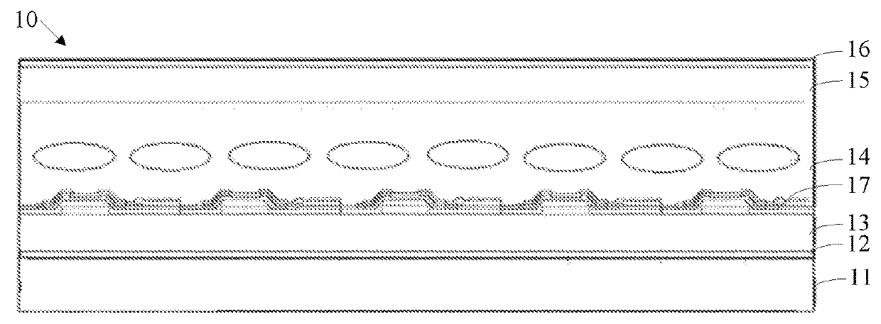
[0048]Please refer to FIG. 1, which is a structural schematic diagram of a liquid crystal apparatus in accordance with a preferred embodiment of the present invention. In the preferred embodiment, the liquid crystal display apparatus 10 includes a graphene LED backlight source 11, a first polarizing film 12, a first substrate 13, a liquid crystal layer 14, a second substrate 15, and a second polarizing film 16.

[0049]The graphene LED backlight source 11 is used for providing a light output having one of red, green, and blue colors. The first polarizing film 12 is used for converting the light output from the backlight source in...


PUM

PropertyMeasurementUnit
wavelengthaaaaaaaaaa
voltageaaaaaaaaaa
wavelengthaaaaaaaaaa

Abstract

A liquid crystal display apparatus is provided. The liquid crystal display apparatus includes a graphene LED backlight source, a first polarizing film, a first substrate, a liquid crystal layer, a second substrate and a second polarizing film. The graphene LED backlight source is used for providing light output, the first polarizing film is used for converting the light output from the backlight source into a polarized light. The liquid crystal layer includes liquid crystal molecules used for deflecting the polarized light from the backlight source to form a polarized output light, and the second polarizing film is used for emitting the polarized output light.

Description

FIELD OF THE INVENTION[0001]The present invention relates to the technical field of a display, and particularly to a liquid crystal display apparatus.BACKGROUND OF THE INVENTION[0002]A conventional liquid crystal display apparatus includes a liquid crystal display panel and a backlight source. The liquid crystal display panel includes an array substrate, a color filter substrate, and a liquid crystal layer disposed between the array substrate and the color filter substrate. The array substrate includes data lines, scan lines, and pixel units formed by the data lines and the scan lines. The color filter substrate includes a common electrode, color filters, etc. The backlight source is used for providing white light output.[0003]In order to realize multi-color display on the liquid crystal display panel, red sub-pixel units, green sub-pixel units, and blue sub-pixel units forming the pixel units are disposed on the array substrate. The red sub-pixel unit cooperates with the red color ...

Claims


Application Information

Patent Timeline
Patent Type & Authority Patents(United States)
IPC IPC(8): G09G3/34H01L33/34G02F1/1362H01L33/40G02F1/1335H01L25/13G09G3/36G02F1/1368
CPCH01L25/13H01L33/40H01L33/34G09G3/3413G02F1/13362G02F1/133621G02F1/136286G09G3/3607G02F1/1368G02F2201/121G02F2201/123G02F2203/34G02F1/133528G02F1/133603G02F2202/02G02F1/133622
Inventor WEI, HONGQUANHU, TAOMA, XIAOLONG
Owner TCL CHINA STAR OPTOELECTRONICS TECH CO LTD
Why Eureka
Try Eureka