

Rigid joint assembly
a joint assembly and rigid technology, applied in the direction of cable junctions, submarine cables, electric cable installations, etc., can solve the problems of pressure gradient along the electrical core, failure under operation, and unfavorable scenario, so as to facilitate mounting of the casing assembly and effectively prevent the movement of the insulation system
- Summary
- Abstract
- Description
- Claims
- Application Information
AI Technical Summary
Benefits of technology
Problems solved by technology
Method used
Image


Examples
Embodiment Construction
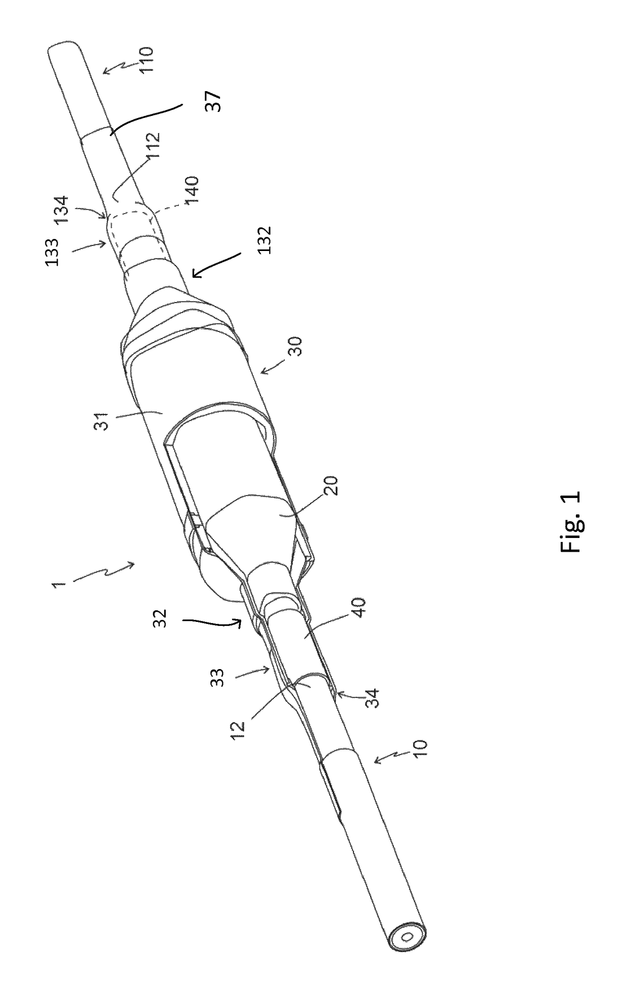
[0039]In FIG. 1 is illustrated an example of a rigid joint assembly 1 comprising a joint connection 20 inside of which the core end of a first electric cable 10 and the core end of a second electric cable 110 are connected. The cables are medium or high voltage cables suitable for submarine installation. The cables are preferably direct current, DC, cables. The joint connection is e.g. a pre-fabricated joint of the type described above, comprising a pre-moulded / pre-fabricated rubber joint body that is used to restore the insulation system where the two core ends are jointed. The rigid joint assembly 1 further comprises first and second outer cable entry parts 33 and 133 comprising a respective opening 34, 134 for the respective cable, a casing assembly 30 inside of which the joint connection 20 is provided and which casing assembly 30 comprises a casing body 31 and first and second inner cable entry parts 32, 133. The first outer cable entry part 33 comprises a first insulation syst...
PUM
| Property | Measurement | Unit |
|---|---|---|
| thickness | aaaaa | aaaaa |
| hydrostatic pressure | aaaaa | aaaaa |
| depths | aaaaa | aaaaa |
Abstract
Description
Claims
Application Information