Knob and input device

a technology of input device and knob, which is applied in the field of knobs, can solve the problems that the touch panel-equipped display cannot be operated, and achieve the effect of preventing the occurrence of non-detection and erroneous detection of the touch of the finger on the knob

Active Publication Date: 2022-01-11
MITSUBISHI ELECTRIC CORP
View PDF9 Cites 3 Cited by
  • Summary
  • Abstract
  • Description
  • Claims
  • Application Information

AI Technical Summary

Benefits of technology

[0008]According to the present invention, the occurrence of non-detection and erroneous detection of a touch of a finger on the knob can be prevented.

Problems solved by technology

Since each touch panel-equipped display does not have an uneven shape on a surface thereof, touch panel-equipped displays cannot be operated unless they are being visually recognized.

Method used


Image

  • Knob and input device
  • Knob and input device
  • Knob and input device

Examples


embodiment 1

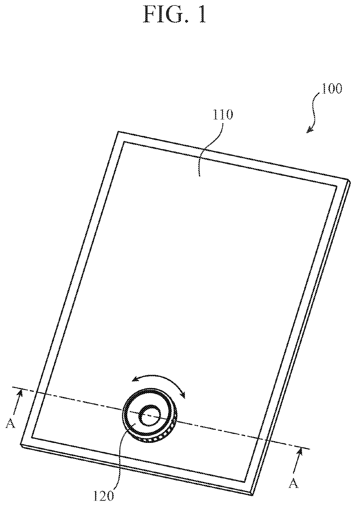
[0015]FIG. 1 is a perspective view of an input device 100 according to the embodiment 1.

[0016]The input device 100 includes a touch panel-equipped display 110 and a knob 120. The touch panel-equipped display 110 includes a capacitive type touch panel 111 (hereinafter referred to as “touch panel 111”), and a display (not illustrated). The display is integral with the touch panel 111.

[0017]The knob 120 is fixed onto the touch panel 111. The knob 120 is shaped like a ring. The knob 120 is constructed in such a way as to be rotatable in a direction of a double-headed arrow shown in FIG. 1. Since the touch panel 111 is exposed inside a ring in the knob 120, information displayed on the display can be visually recognized.

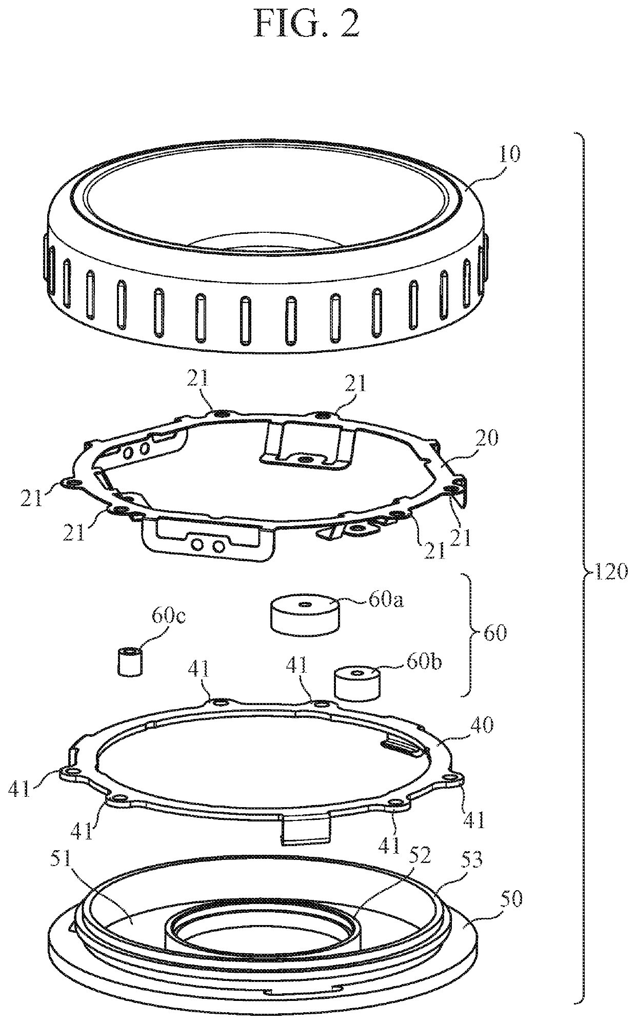
[0018]FIG. 2 is an exploded view of the knob 120 according to the embodiment 1.

[0019]The knob 120 mainly includes an operation portion 10, a conductive connecting member 20, conducting terminal portions 60, a rotary member 40, and a rotary supporting member 50.

[0020]FIG. ...


PUM


Abstract

It includes a knob including: an operation portion comprised of a ring-shaped conductive material, a rotational operation being performed on the operation portion; a rotary supporting member comprised of a ring-shaped non-conductive material and fixed onto a capacitive type touch panel, for rotatably supporting the operation portion; a ring-shaped concave groove disposed in the rotary supporting member; and a conductive conducting terminal portion electrically connected to the operation portion and rotating inside the concave groove integrally with the operation portion, the position of the conducting terminal portion being detected by the touch panel, wherein the conducting terminal portion is comprised of a plurality of conducting terminal portions, surfaces of the conducting terminal portions being in contact with the concave groove, at least two of the surfaces of the conducting terminal portions being different in contact area from each other.

Description

TECHNICAL FIELD[0001]The present invention relates to a knob for operating a touch panel, and an input device in which the knob is fixed to the touch panel.BACKGROUND ART[0002]In recent years, many displays each with a capacitive type touch panel (hereinafter each referred to as “touch panel-equipped display”) have been adopted for navigation devices, audio devices, center displays, and so on which are mounted in vehicles. Since each touch panel-equipped display does not have an uneven shape on a surface thereof, touch panel-equipped displays cannot be operated unless they are being visually recognized.[0003]Patent Literature 1 discloses an input device in which a knob is fixed to a touch panel-equipped display in order to improve the ease of operation of the touch panel-equipped display. The knob includes a gripping portion for allowing a user to perform an operation, and a terminal portion that serves as a contact surface for the touch panel. When the user's finger touches the gri...

Claims


Application Information

Patent Timeline
Patent Type & Authority Patents(United States)
IPC IPC(8): G06F3/039G06F3/0362G06F3/044
CPCG06F3/0393G06F3/0362G06F3/044
Inventor TAKAOKA, SHINYATSUKAGUCHI, AKINORI
Owner MITSUBISHI ELECTRIC CORP
Why Eureka
Try Eureka