Check patentability & draft patents in minutes with Patsnap Eureka AI!

Adjustable brake lever sensor system

a technology of brake lever and sensor, which is applied in the field of electric transportation, can solve the problems of increased pressure from the brake pads on the bicycle rim, significant energy loss, and increased pressure on the brake pads

Active Publication Date: 2022-03-29
MSNS LLC
View PDF6 Cites 0 Cited by
  • Summary
  • Abstract
  • Description
  • Claims
  • Application Information

AI Technical Summary

Benefits of technology

Enables users to customize the brake lever position for comfort and efficiency, maintaining consistent sensor performance and integrating seamlessly with existing systems, thereby enhancing user experience and system compatibility.

Problems solved by technology

Urban drive cycles have a considerable amount of acceleration and decelerating periods due to traffic control systems in place around towns and cities, and therefore, when decelerating, significant energy is lost.
Similarly, off road cycles also have a considerable need for acceleration and deceleration due to climbing and descending hills.
As the tension in the brake cable increases, this increased tension results in increased pressure from the brake pads onto the bicycle rim, or increased pressure of the brake pads onto a brake disc, in the case of a disc brake system.
The proportional electric braking system and the sensor coupled to the lever do not operate as the mechanical cable braking system would, and do not offer a method of setting the brake lever to a preferred initial position, as there is no mechanical cable and cable sheath.

Method used


Image

  • Adjustable brake lever sensor system
  • Adjustable brake lever sensor system
  • Adjustable brake lever sensor system

Examples


Embodiment Construction

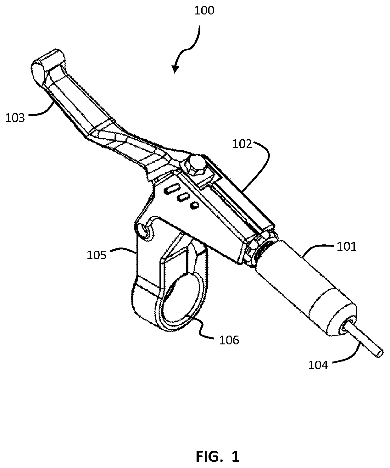
[0020]In some embodiments of the present invention, as seen in FIG. 1, an adjustable handlebar mounted brake lever system 100 for a proportional electric braking system may have a brake lever assembly 102 coupled to a brake lever sensor assembly 101. The brake lever assembly may include a lever 103 adapted coupled to a main body 105 which includes a handlebar opening 106. A wire assembly 104 may extend from the sensor assembly 101. In some aspects, the brake lever assembly may be a standard brake lever assembly as used with mechanical cable braking systems. In some aspects, the main body 105 is mounted onto a bicycle handlebar, with a portion of the handlebar extending through the handlebar opening 106. In some aspects, the handlebar mounted brake lever system may be used on scooters, motorcycles, or other similar vehicles.

[0021]FIG. 2A illustrates a cross-sectional view of an adjustable handlebar mounted brake lever system 100 for a proportional electric braking system according to...


PUM


Abstract

An adjustable hand brake lever assembly for a proportional electric braking system for a bicycle or other vehicle. The brake lever assembly may include a sensor assembly which is adapted for use with a standard brake lever assembly as used with mechanical cable braking systems. The sensor assembly may be replaced as a unit. The sensor assembly is adapted to allow for setting the reach adjustment, allowing a user to set a preferred initial position. The adjustable brake lever assembly may be coupled to a control electronic module and a regenerative braking system on a bicycle.

Description

CROSS-REFERENCE TO RELATED APPLICATIONS[0001]This application claims priority to U.S. Provisional Patent Application No. 62 / 785,263 to Saiki, filed Dec. 27, 2019, which is hereby incorporated by reference in its entirety.BACKGROUNDField of the Invention[0002]The present invention relates to electric transport, and more specifically to a hand brake lever with sensor. Examples of such electric transport include electric bicycles, scooters, and tricycles.Description of Related Art[0003]Motivated by the environmental, public health, ecological, and carbon-footprint issues associated with gasoline-powered automobiles, researchers, governments, and society as a whole have been engaged in a search for viable alternatives. Electric bicycles (e-bikes), which are propelled by a combination of pedaling and battery-powered electric motors, are a promising alternative to automobile transportation. Their primary advantages include lower purchase and operating costs compared to cars, ability to tr...

Claims


Application Information

Patent Timeline
Patent Type & Authority Patents(United States)
IPC IPC(8): B62L3/02G01D5/14B60T7/08
CPCB62L3/02B60T7/085G01D5/142B60T7/102B60T11/16B60T1/10F16D61/00B60T2270/604G01D5/145B62J45/422B62K23/06H04M1/575H04M1/724H04M1/72484H04M3/42042H04M3/42059G06F3/017G06N20/00H04M3/4365H04M2203/25
Inventor SAIKI, NEAL
Owner MSNS LLC
Features
  • R&D
  • Intellectual Property
  • Life Sciences
  • Materials
  • Tech Scout
  • Unparalleled Data Quality
  • Higher Quality Content
  • 60% Fewer Hallucinations
Learn More