Smoothing roller in a printing unit of a rotary printing machine

Inactive Publication Date: 2001-09-13
MANROLANAD AG
View PDF0 Cites 2 Cited by
  • Summary
  • Abstract
  • Description
  • Claims
  • Application Information

AI Technical Summary

Problems solved by technology

Irrespective of whether a printing ink has to contain a separating agent in order to be particularly suitable for dry offset printing or whether printing is carried out using a dampening medium, there is the problem, particularly in the case of short inking units, of obtaining as smooth an ink film as possible on the form cylinder, in order to achieve high printing quality.

Method used


Image

  • Smoothing roller in a printing unit of a rotary printing machine
  • Smoothing roller in a printing unit of a rotary printing machine
  • Smoothing roller in a printing unit of a rotary printing machine

Examples


Embodiment Construction

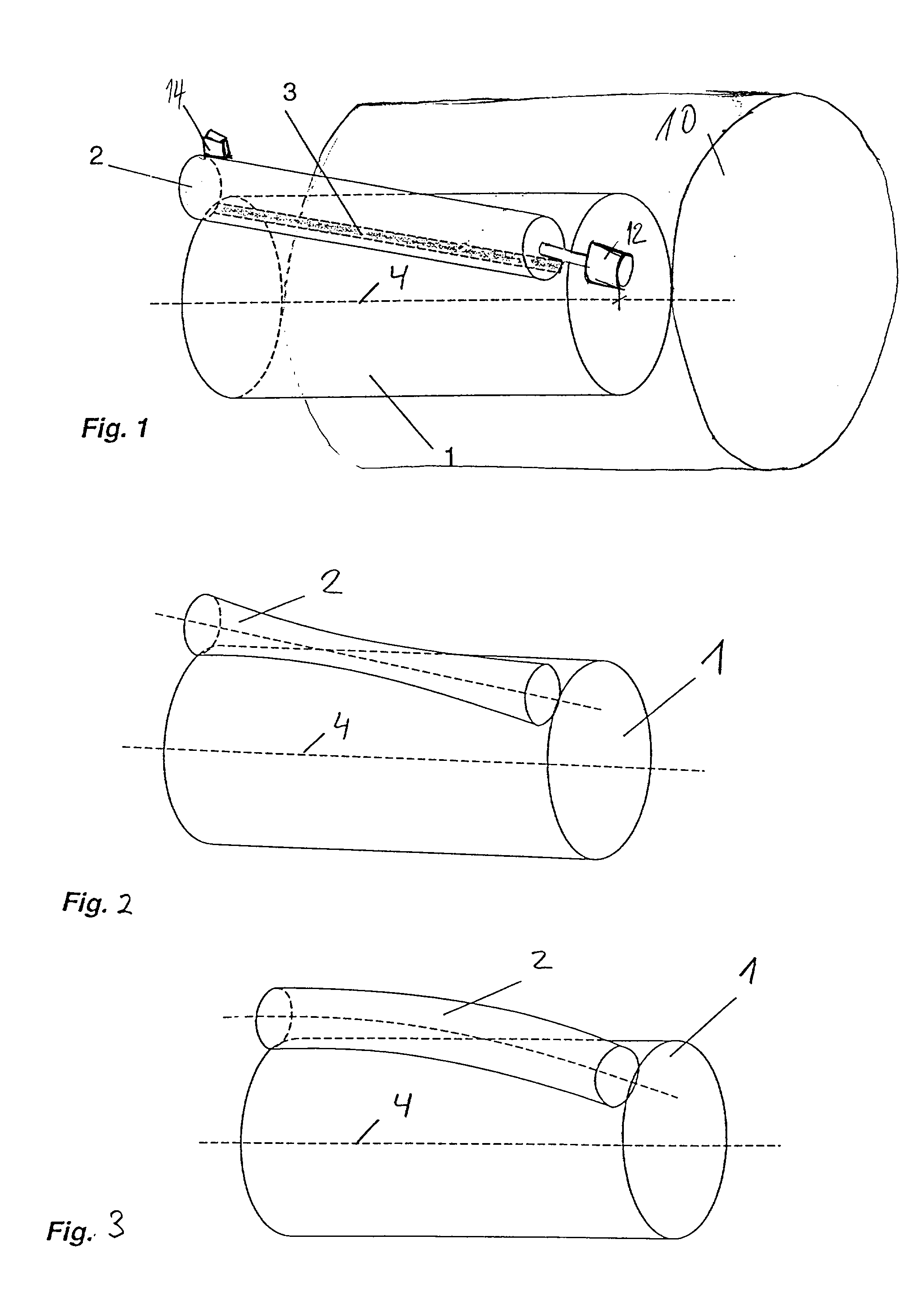
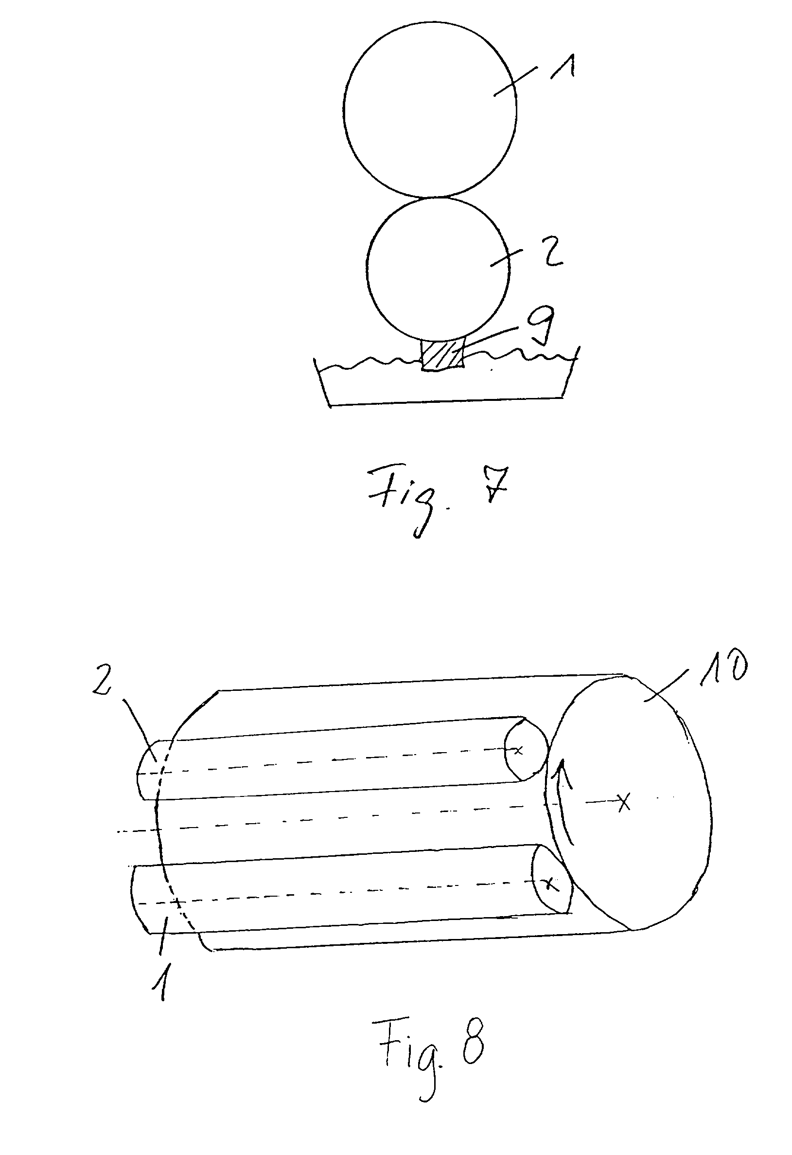
[0024] Referring to FIG. 1, an ink applicator roller 1 according to the present invention is arranged on a form roller 10 in an inking unit of a printing machine such, for example, as a short inking unit of an offset printing machine or a printing machine for direct printing. A smoothing roller 2 designed as a rider roller is applied to the ink applicator roller 1 obliquely to the longitudinal axis of the ink applicator roller 1. Referring to FIG. 2, the smoothing roller may be concavely curved so that the diameter of the smoothing roller 2 toward its center is narrower than the diameter towards the sides thereof. Referring to FIG. 3, the smoothing roller 2 may be bent elastically about its longitudinal axis. For illustrative purposes, FIGS. 2 and 3 to show exaggerated versions of the concavity and the bend of the longitudinal axis. The smoothing roller 2 may comprise a combination of the two measures illustrated in FIGS. 2 and 3. These measures ensure a contact surface 3 between th...


PUM


Abstract

The present invention provides a smoothing roller for a printing unit of a rotary printing machine. The smoothing roller is applied to the form cylinder downstream of the ink applicator roller in relation to the direction of rotation of the form cylinder or onto the ink applicator roller itself. The smoothing roller smooths the ink film on the form cylinder or on the ink applicator roller. The outer surface of the smoothing roller has an ink-repelling characteristic. The ink-repelling characteristic is effected by a liquid ink-repelling material such as a separating agent or a dampening medium that is applied to the outer surface of the smoothing roller or by an outer surface of the smoothing roller comprising an ink-repelling material. The two measures for effecting the ink-repellant characteristic of the smoothing roller may also be provided in combination with one another.

Description

[0001] 1. Field of the Invention[0002] The invention relates to a smoothing roller in a printing unit of a rotary printing machine.[0003] 2. Description of the Related Art[0004] Reference DE 44 24 913 A1 discloses a short inking unit for the inking of a form cylinder for dry offset printing. The short inking unit has an ink transfer roller and an ink applicator roller. The ink transfer roller is designed as a screen roller. Between the depressions on the outer surface of the screen roller there are webs which have high affinity to a separating agent, for example silicone oil. For this purpose, the hard-ceramic material of the ink transfer roller is impregnated with silicone oil, or silicone rubber or fluorosilicone rubber is embedded into the hard-ceramic material. The depressions are lined with an ink-friendly coating repelling the separating agent. The design of the ink transfer roller is intended to avoid ink transfer difficulties when printing inks mixed a separating agent are u...

Claims


Application Information

Patent Timeline
Patent Type & Authority Applications(United States)
IPC IPC(8): B41F31/00B41F31/14B41F31/26
CPCB41F31/00
Inventor BACHMEIR, XAVERFISCHER, WOLFRAMFELLER, BERNHARD
Owner MANROLANAD AG
Why Eureka
Try Eureka