Axial ball transfer assemblies

Inactive Publication Date: 2002-06-06
THOMSON IND INC
View PDF0 Cites 18 Cited by
  • Summary
  • Abstract
  • Description
  • Claims
  • Application Information

AI Technical Summary

Problems solved by technology

This structure, however, is difficult to efficiently manufacture because of the complex molds required.
These bearing assemblies, particularly the assembly shown in the '992 patent, are even more difficult to manufacture because a plurality of ball tracks are being formed.
This technique is both time consuming and inefficient.
In addition to the problems associated with assembling and positioning the axial and inner guides, bearing assemblies making use of typical individual bearing plates tend to have alignment and positioning problems associated therewith.
If these bearing plates are not properly and securely positioned, the bearing assembly will not operate efficiently and may cau

Method used


Image

  • Axial ball transfer assemblies
  • Axial ball transfer assemblies
  • Axial ball transfer assemblies

Examples


Embodiment Construction

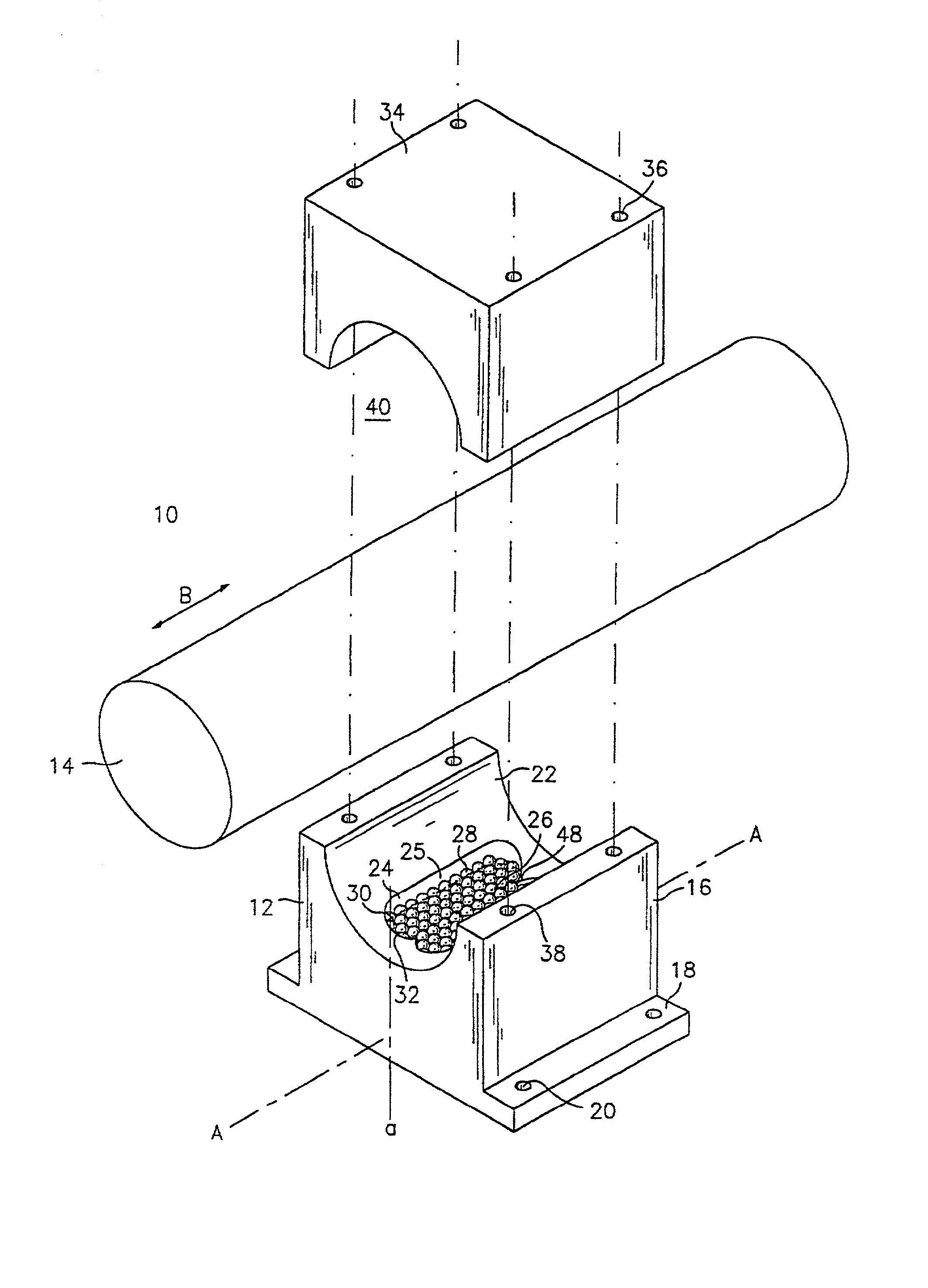
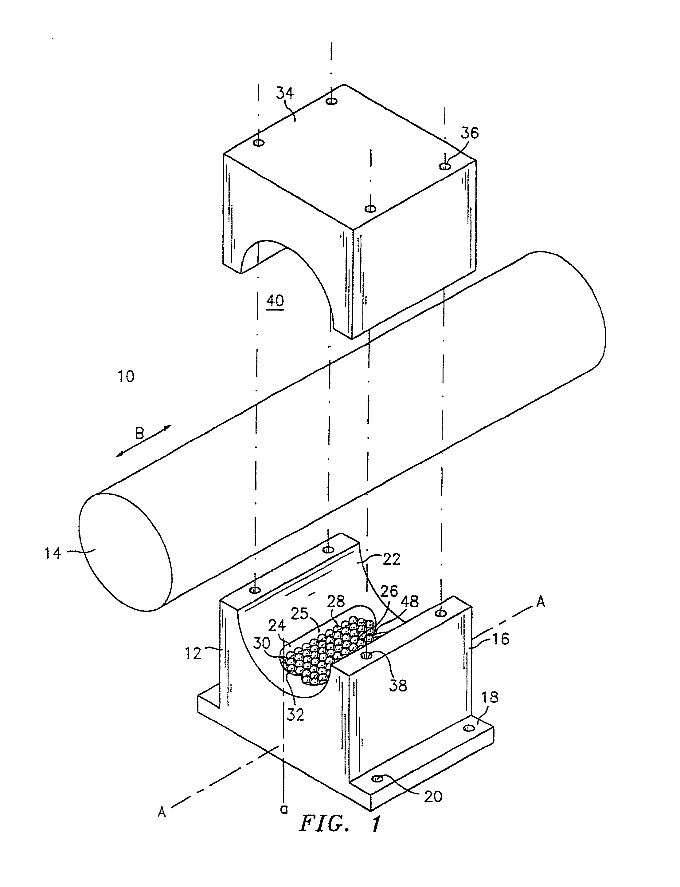
[0049] Referring now to the drawings, wherein like reference numerals identify similar structural elements of the subject invention, there is illustrated in FIG. 1 an axial ball transfer assembly, such as, for example, a bearing assembly 10 having a block 12 for use in open and closed type bearing assemblies and constructed in accordance with one embodiment of the present invention.

[0050] Bearing assembly 10 may have a portion constructed as a carriage, pillow block, outer housing, etc., for longitudinal movement or rotational movement along a support member such as, for example, an elongated shaft, rail, spline, etc. In the automotive technologies, bearing assembly 10 may be utilized in rack and pinion type apparatus for reducing frictional forces in particular situations, such as, for example, power failures, etc. Bearing assembly 10 supports a shaft 14 which may be in communication with and / or form a portion of a power steering assist mechanism (not shown) and / or a steering colum...


PUM


Abstract

A bearing assembly is disclosed that 410 includes at least one ball track having a load bearing portion, a return portion and a turnaround portion interconnecting the load bearing and return portions. A plurality of bearing balls are disposed in the ball tracks. At least a portion of the ball tracks are configured for unguided recirculation of the bearing balls. The bearing assembly may include a pair of ball tracks separated by a center rib. In an alternate embodiment, the bearing assembly includes at least one island disposed in at least a portion of the ball tracks. The islands facilitate recirculation of the bearing balls in the ball tracks. In another alternate embodiment, a bearing assembly is provided that includes a rail. A bearing carriage is configured to move along the rail. At least one ball track is disposed adjacent the rail and the bearing carriage. The ball tracks include a load bearing portion, a return portion and a turnaround portion interconnecting the load bearing and return portions. A plurality of bearing balls are disposed in the ball tracks. The ball tracks are configured for unguided recirculation of the bearing balls. The bearing assembly may include at least one insert having at least a portion of the ball tracks formed therein.

Description

[0001] 1. Field of the Invention[0002] This invention relates to bearing assemblies, and more particularly to ball track bearing assemblies that reduce friction associated with movement of two bodies relative to each other.[0003] 2. Description of the Related Art[0004] Bearing assemblies may be of the type which support a carriage or block for movement along a support member such as an elongated shaft, rail or spline to reduce friction associated with longitudinal or rotational motion. These bearing assemblies can be of the open or closed type.[0005] Bearing assemblies also contemplated by the present invention generally include an outer housing and a block dimensioned for insertion into the outer housing. The block defines a plurality of longitudinal planar faces each having at least one ball track in a loop configuration for containing and recirculating bearing balls. The ball tracks include open portions which facilitate load transfer from the supporting shaft to load bearing str...

Claims


Application Information

Patent Timeline
IPC IPC(8): F16C13/04F16C19/50F16C29/06
CPCF16C13/04F16C19/50F16C29/0685F16C29/0676F16C29/0616F16C29/06
Inventor LYON, GREGORY S.NG, ALISONKIM, ERIC
Owner THOMSON IND INC
Why Eureka
Try Eureka