Scanning head module

a head module and scanning head technology, applied in the field of scanning systems, can solve the problems of unacceptable output images and electrical magnetic interference becoming more serious in the high-speed scanning system

Inactive Publication Date: 2002-10-24
TRANSPACIFIC SYST
View PDF2 Cites 0 Cited by
  • Summary
  • Abstract
  • Description
  • Claims
  • Application Information

AI Technical Summary

Benefits of technology

[0008] It is another objective of the present invention to provide a scanning head module, wherein an optical system, a photosensitive detector and a processing circuit all integrated into one module installed into a housing. Thus, the shielding of the scanning head module to prevent the electrical magnetic interference (EMI) is simplified.
[0009] It is a further objective of the present invention to provide a scanning head module, which integrates a photosensitive detector and a processing circuit in a main board. Therefore, a signal transmission line and a driving device for driving the processing circuit between the photosensitive detector and the processing circuit could be removed and the electrical magnetic interference (EMI) of the output signal of the photosensitive detector is significantly eliminated.
[0012] In order to achieve the above objectives of this invention, the present invention provides a scanning head module comprising of, a light source and a housing with an optical system and a main board installed therein. The light source illuminates a document to be scanned. The optical system includes a set of mirrors and a lens assembly. The main board includes a photosensitive detector and a processing circuit. The illumination light coming from the document is guided by the set of mirrors and focused by the lens assembly onto the photosensitive detector. The processing circuit processes the signal received from the photosensitive detector. Since the photosensitive detector and the processing circuit are integrated in the main board, the output signal of the photosensitive detector could be transmitted to the processing circuit without through a transmission line. Therefore, the electrical magnetic interference of the output signal of the photosensitive detector is significantly eliminated.

Problems solved by technology

Consequently, the analog signal transmitted in the cable 21 is easily subject to the electrical magnetic interference (EMI), resulting in an unacceptable output image.
The electrical magnetic interference becomes more serious in a high speed scanning system.

Method used


Image

  • Scanning head module
  • Scanning head module
  • Scanning head module

Examples


Embodiment Construction

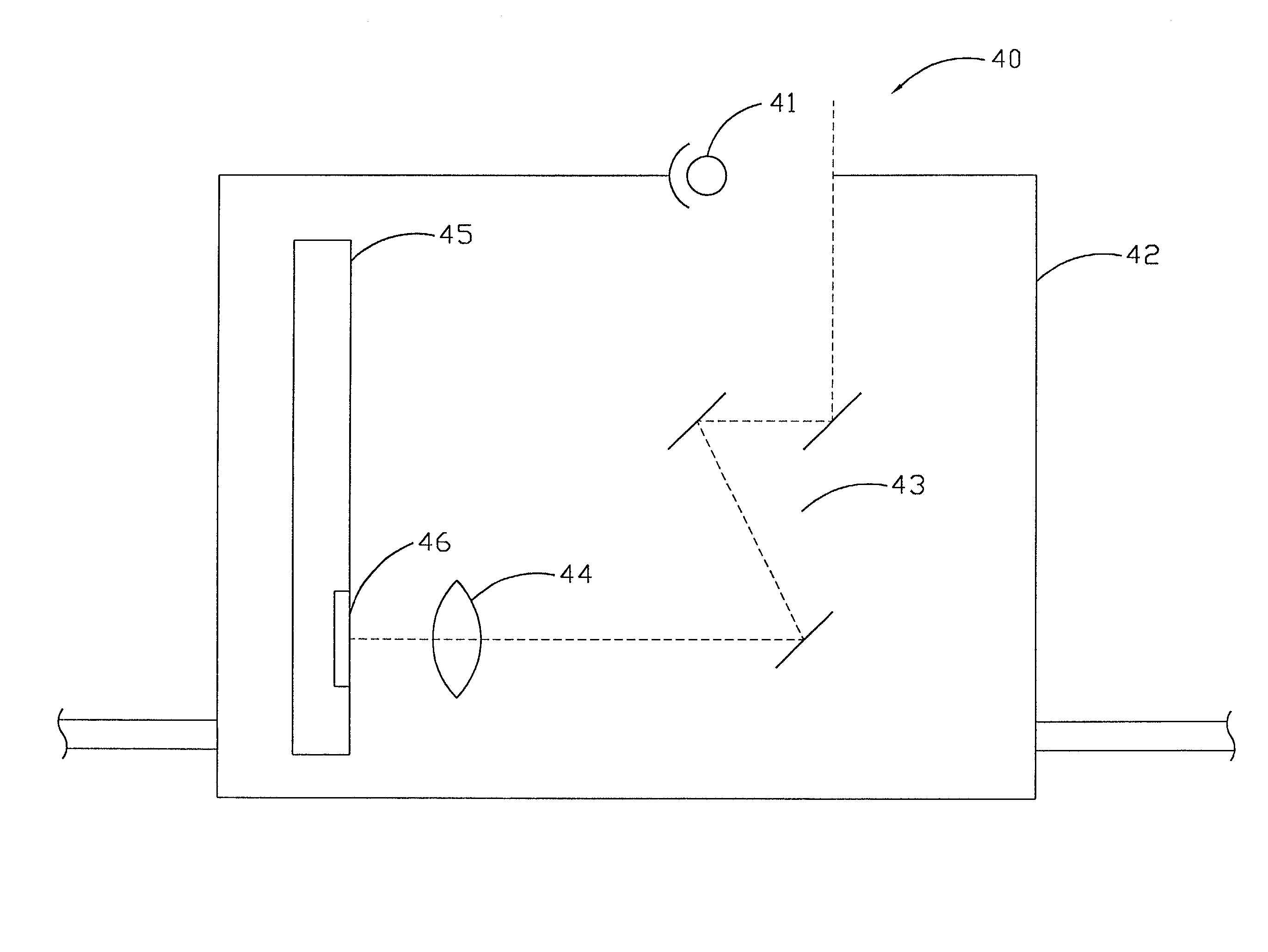
[0019] Please refer to FIG. 4. FIG. 4 is a schematically cross-sectional view of a scanning head module 40 in accordance with the present invention. The scanning head module 40 comprises: a light source 41 and a housing 42 including an optical system formed of a set of mirrors 43 and a lens assembly 44 and a main board 45. A light emitting diode (LED) can be used as the light source 41. A cold cathode fluorescent lamp (CCFL) can also be used as the light source 41. The main board 45 can be formed of polycarbonate (PC), and has a photosensitive detector 46, a processing circuit 47, a memory 50, an interface control circuit 51 and a motor control circuit 52 installed thereon.

[0020] The photosensitive detector 46 can be a charge coupled device (CCD), a CMOS sensor and a contact image sensor (CIS). The processing circuit 47 is comprised of an analog-to-digital converter circuit (ADC circuit) 48 and a control circuit 49, such as an application specific integrated circuit (ASIC). Alternat...


PUM


Abstract

A scanning head module is provided. A photosensitive detector and a processing circuit are integrated in one module and installed on a main board so that a signal transmission line and a driving device for driving the processing circuit between the photosensitive detector and the processing circuit could be removed. Thus, the electrical magnetic interference (EMI) of the output signal of the photosensitive detector is significantly eliminated. The shielding of the scanning module for preventing electrical magnetic interference is also simplified.

Description

[0001] 1. Field of the Invention[0002] The present invention relates to a scanning system, and more particularly to a scanning head module of a scanning system.[0003] 2. Description of the Prior Art[0004] Please refer to FIG. 1. FIG. 1 is a schematically cross-sectional view of a prior scanner 10. The scanner 10 comprises a body 11 with a transparent platform 12 on its top end for placing a document to be scanned, and a scanner head 13 is movably installed under the transparent platform 12 for scanning the document placed on the transparent platform 12. The scanner head 13 slides on a belt 14 by way of a transmission means (not shown). The scanner head 13 usually comprises a housing 15 with a light source 16, an optical system including a set of mirrors 17 and a lens 18, a photosensitive detector 19, and a driving device 20 installed therein. The photosensitive detector 19, such as a CCD (charge coupled device), detects the image light focused thereon by the optical system reflected...

Claims


Application Information

Patent Timeline
Patent Type & Authority Applications(United States)
IPC IPC(8): H04N1/03
CPCH04N1/00976H04N2201/02495H04N1/03
Inventor CHIU, CHUI-KUEI
Owner TRANSPACIFIC SYST
Why Eureka
Try Eureka