Fuel injection valve

a fuel injection valve and valve body technology, applied in the direction of fuel injection apparatus, fuel feed system, spraying apparatus, etc., can solve the problems of increased fuel consumption, fixed swirl angle, and inability to adapt to different operating conditions,

Inactive Publication Date: 2003-09-11
ROBERT BOSCH GMBH
View PDF4 Cites 0 Cited by
  • Summary
  • Abstract
  • Description
  • Claims
  • Application Information

AI Technical Summary

Problems solved by technology

A disadvantage of the fuel injectors known from the publication cited above is in particular the fixedly set swirl angle, which cannot be adapted to the different operating states of an internal combustion engine such as partial load and full load oper...

Method used


Image

  • Fuel injection valve
  • Fuel injection valve
  • Fuel injection valve

Examples


Embodiment Construction

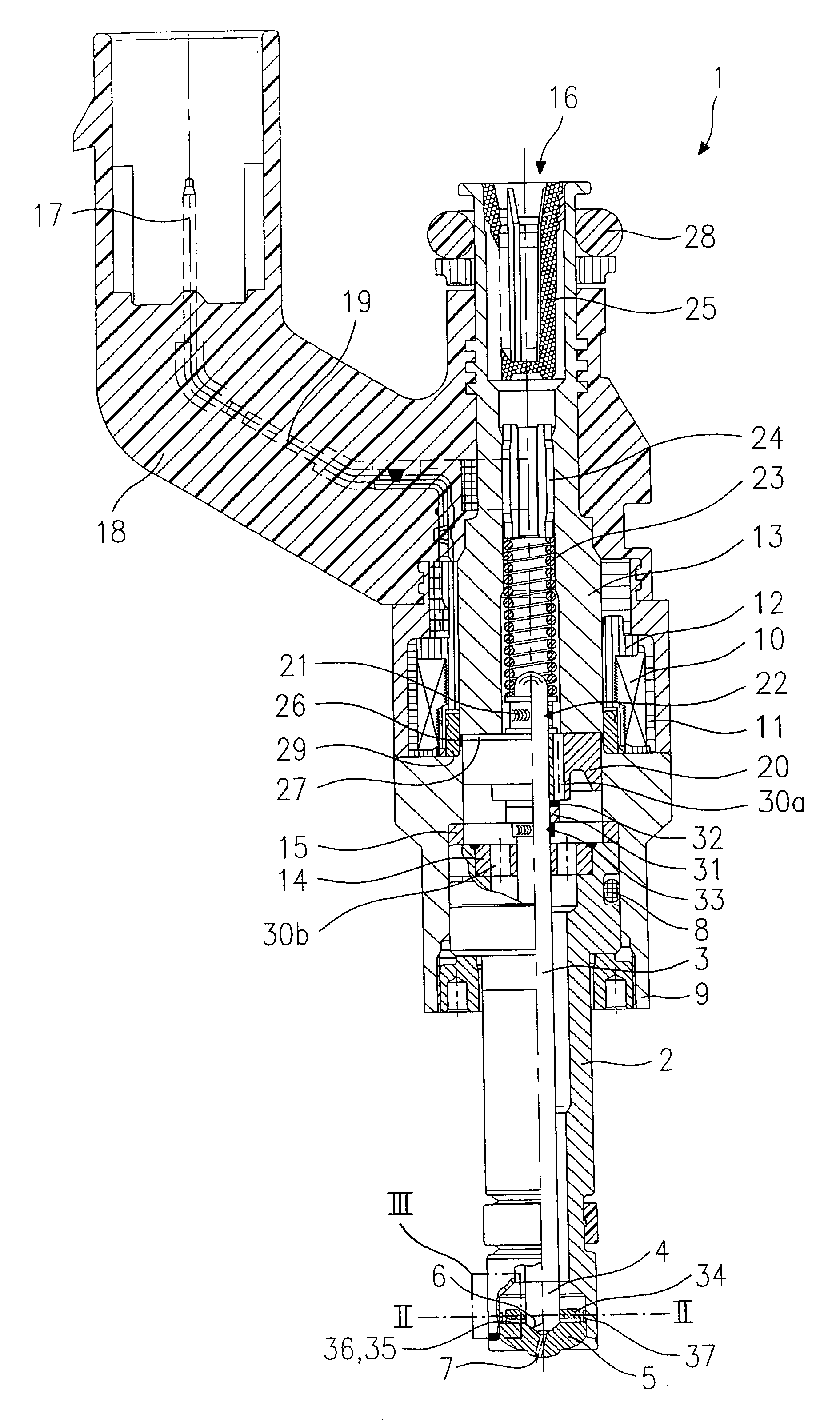
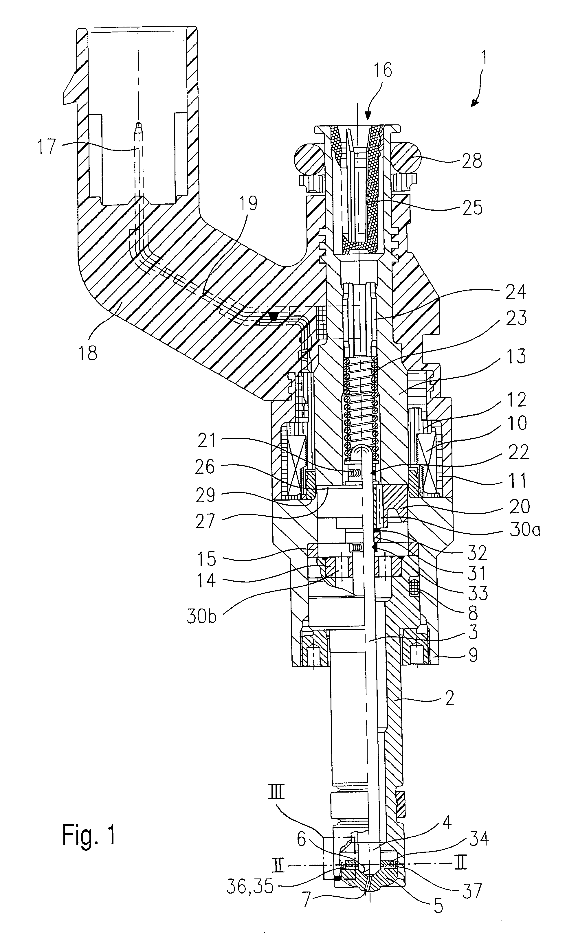
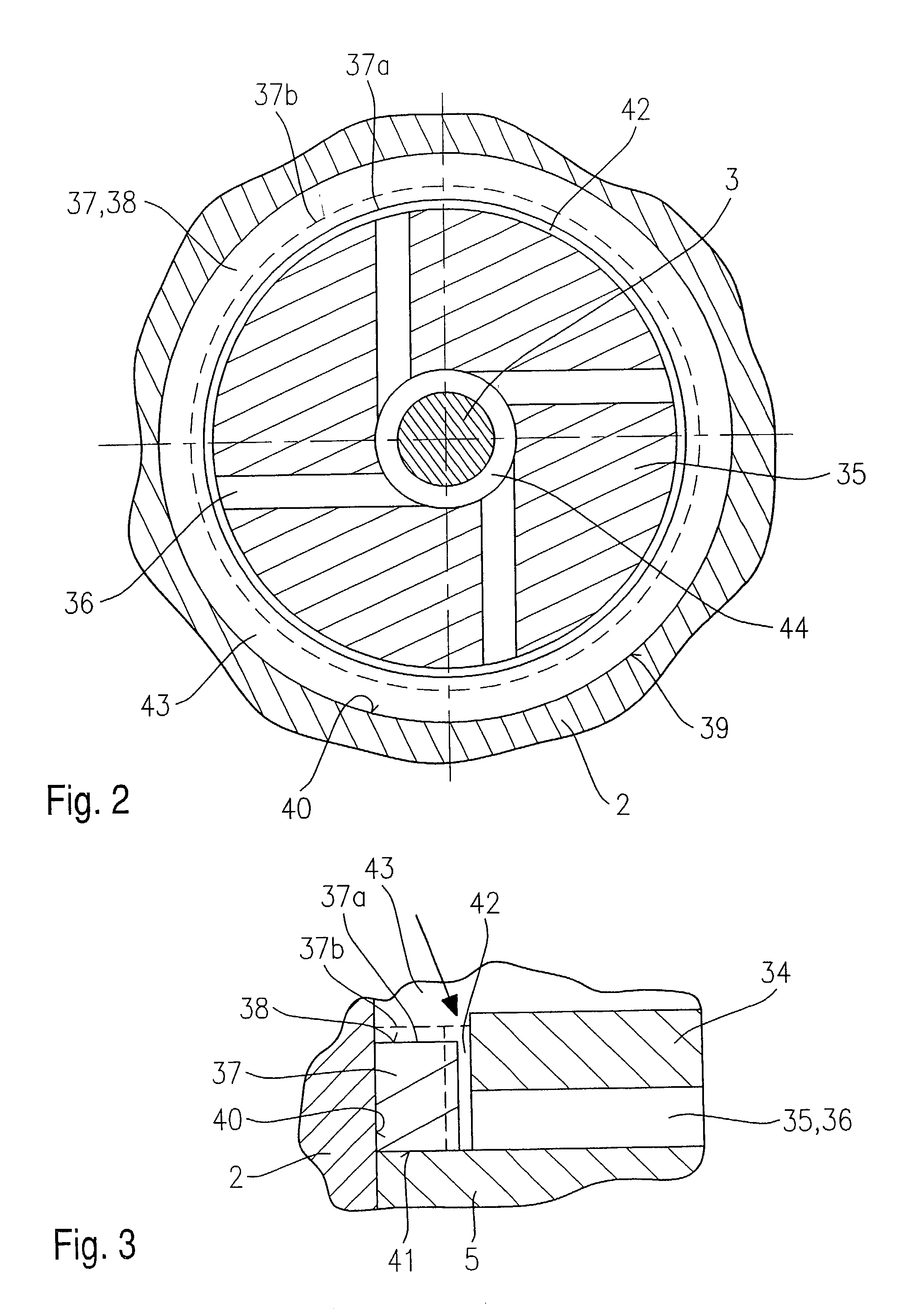
[0014] Before an exemplary embodiment of a fuel injector 1 according to the present invention is described in greater detail based on FIGS. 2 and 3, the essential components of fuel injector 1 according to the present invention will be explained briefly in general terms.

[0015] Fuel injector 1 is designed in the form of a fuel injector for fuel injection systems of mixture-compressing, spark-ignited internal combustion engines. Fuel injector 1 is suitable in particular for the direct injection of fuel into a combustion chamber (not shown) of an internal combustion engine.

[0016] Fuel injector 1 includes a nozzle body 2 in which valve needle 3 is situated. Valve needle 3 is mechanically linked with a valve-closure member 4, which cooperates with a valve-seat surface 6 situated on a valve-seat member 5 to form a sealing seat. In the exemplary embodiment, fuel injector 1 is an inwardly opening fuel injector 1 having at least one spray-discharge orifice 7. Nozzle body 2 is sealed off from...


PUM


Abstract

A fuel injector (1), in particular for the direct injection of fuel into the combustion chamber of a mixture-compressing, spark-ignited internal combustion engine includes an actuator (10), a valve needle (3) actuatable by the actuator (10) for operating a valve-closure member (4), which, together with a valve-seat surface (6) forms a sealing seat and a swirl disk (35) having at least one swirl channel (36). An elastic fuel metering ring (37) is situated in a recess (43) of a nozzle body (2) of the fuel injector (1) in such a manner that a metering cross-section of the at least one swirl channel (36) is variable as a function of a fuel pressure prevailing in the fuel injector (1) during operation.

Description

BACKGROUND INFORMATION[0001] The present invention is directed to a fuel injector according to the definition of the species in the main claim.[0002] A fuel injector for the direct injection of fuel into the combustion chamber of a mixture-compressing, spark-ignited internal combustion engine, the fuel injector including a guide and seat area formed by three disk-shaped elements at the downstream end of the fuel injector is known from German Patent Application 197 36 682 A1. A swirl element is embedded between a guide element and a valve seat element. The guide element is used to guide an axially movable valve needle that passes through the guide element while a valve closing section of the valve needle cooperates with a valve-seat surface of the valve seat element. The swirl element has an inner opening area with multiple swirl channels that are not connected to the outer circumference of the swirl element. The entire opening area extends completely across the axial thickness of th...

Claims


Application Information

Patent Timeline
IPC IPC(8): F02M51/06F02M61/16F02M61/18
CPCF02M51/0671F02M61/18F02M61/162
Inventor YILDRIM, FEVZIHOHL, GUENTHERHUEBEL, MICHAELKEIM, NORBERT
Owner ROBERT BOSCH GMBH
Why Eureka
Try Eureka