Articulated robot

a robot and articulation technology, applied in the field of articulation robots, can solve the problems of limited environment in which the robot can be used, the plurality of robots are difficult to arrange close to each other, and the robots cannot function as robots by themselves

Active Publication Date: 2004-08-05
TOYOTA JIDOSHA KK +1
View PDF4 Cites 58 Cited by
  • Summary
  • Abstract
  • Description
  • Claims
  • Application Information

AI Technical Summary

Problems solved by technology

Therefore, it is difficult to arrange a plurality of robots close to each other, and therefore the environment in which the robot can be used is limited.
However, they do not function as a robot by themselves and require a long arm.
In the example described in JP Patent Publication (Kokai) No....

Method used


Image

  • Articulated robot
  • Articulated robot
  • Articulated robot

Examples


Embodiment Construction

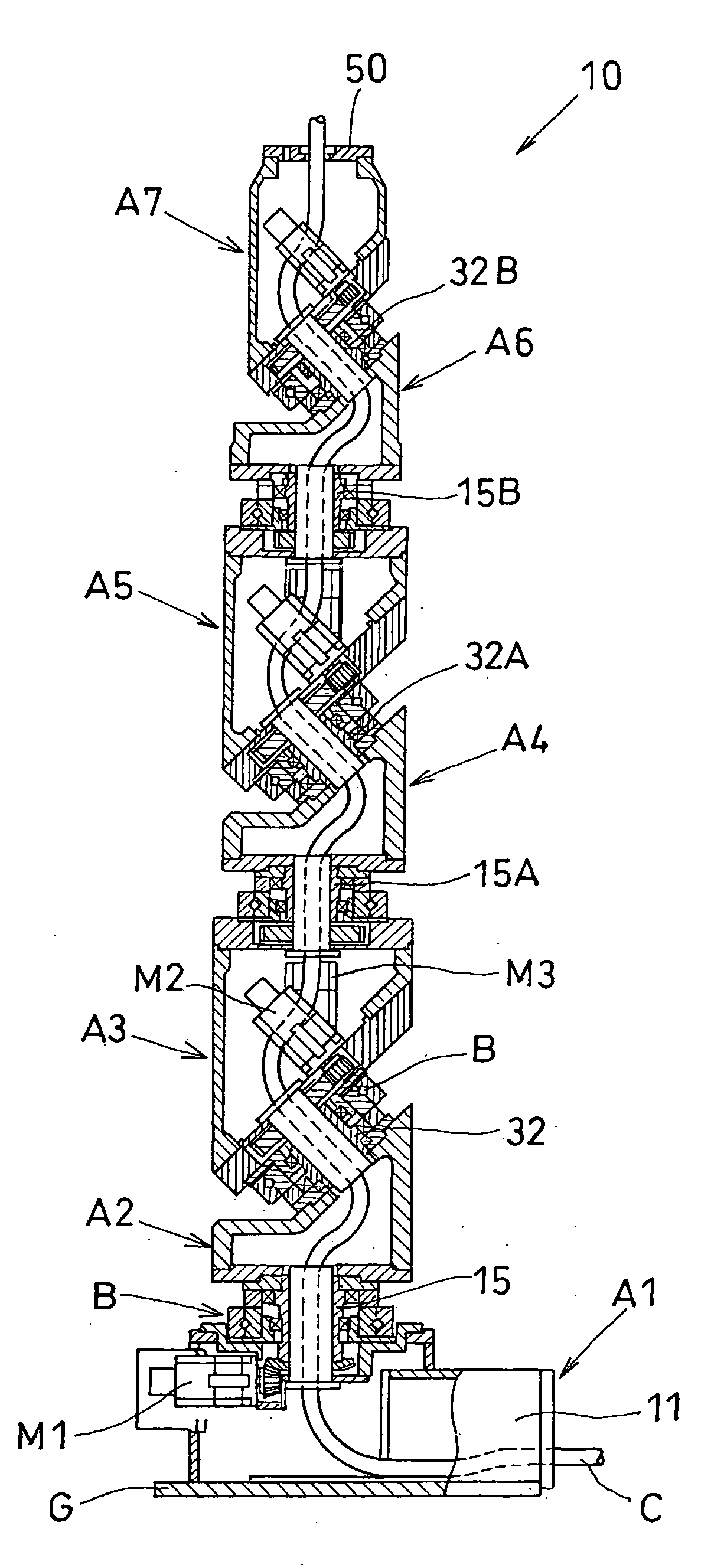
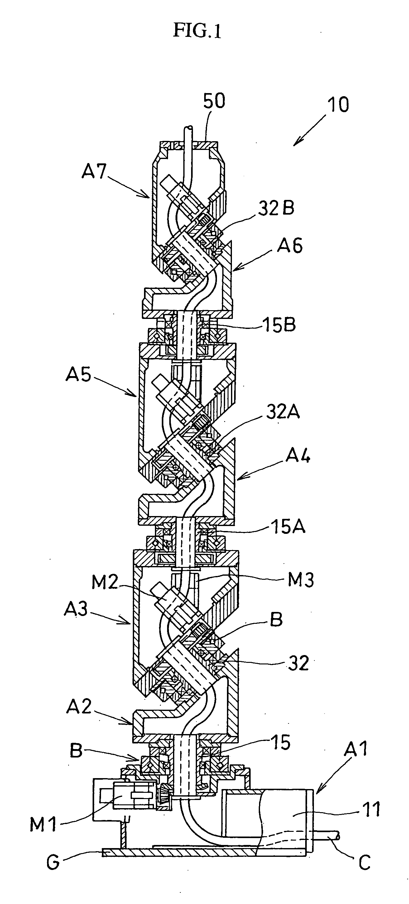
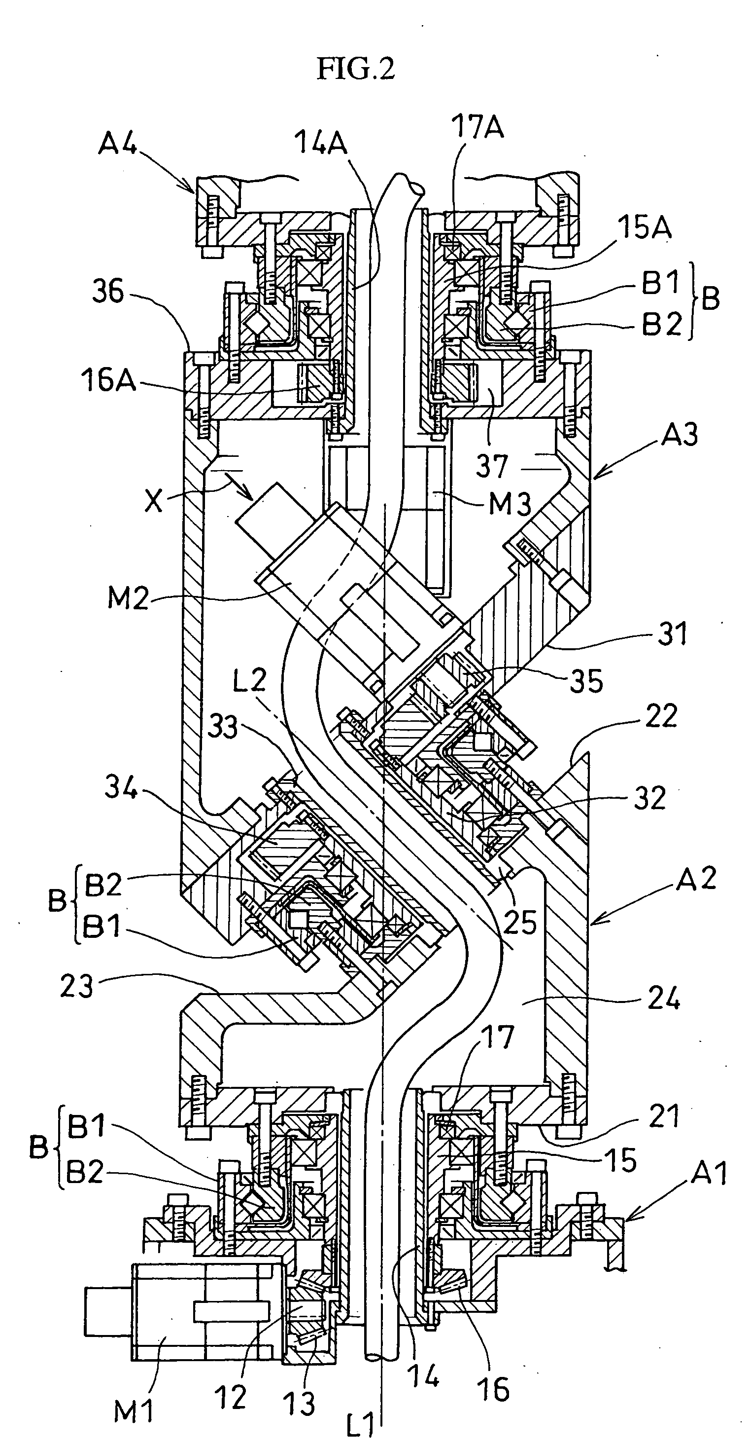
[0028] Hereafter the present invention will be described by referring to embodiments. FIGS. 1 and 2 illustrate an articulated robot 10 according to one embodiment of the present invention. In this embodiment, the robot has six joints and seven joint arms. A first joint arm A1 is fixed on a base G to function as a machine table. It is provided with a motor M1 as a driving power source and an introduction opening 11 for cables. The motor M1 has built inside an encoder and a braking device. The motor has a rotating drive shaft 12 disposed in a horizontal direction, and a bevel gear 13 is mounted on the tip of the drive shaft.

[0029] A hollow fixed shaft 14 is vertically disposed in the first joint arm A1, and a horizontal rotating shaft 15 (corresponding to "a first rotating shaft" of the present invention) is fitted about the shaft 14. A bevel gear 16 is mounted at the lower end of the horizontal rotating shaft 15 and is engaged with the bevel gear 13 mounted on the rotating drive shaf...


PUM


Abstract

An articulated robot capable of reducing dead space while maintaining a wide operating area and simplifying a power transmission system necessary for moving each joint. A plurality of joint arms A1 to A7 are connected via first rotating shafts 15, 15A, and 15B as horizontal rotating shafts and via second rotating shafts 32, 32A, and 32B as inclined rotating shafts alternately. A motor M for driving the rotating shaft and a speed-reducing mechanism are provided for each rotating shaft.

Description

[0001] 1. Field of the Invention[0002] The present invention relates to an articulated robot mainly intended for industrial use.[0003] 2. Background Art[0004] Polar coordinate articulated robots are often used as industrial robots. FIG. 8 shows one example thereof, which comprises a first arm 1 swingably attached to a base 3, a second arm 2 swingably attached to the tip of the first arm 1, and a multidirectional wrist mechanism 4 attached to the tip of the second arm. A necessary tool hand such as a welding gun or a gripper is mounted on the tip of the wrist mechanism 4 to perform robotic operations.[0005] Patent Document 1 (JP Patent Publication (Kokai) No. 63-288690 A (1988)) discloses an example of the wrist mechanism, which comprises a central cylindrical body and a first and a second end cylindrical body provided at each end thereof. These three members are rotatably connected to each other such that the axes of the individual cylindrical bodies are perpendicular to each other,...

Claims


Application Information

Patent Timeline
IPC IPC(8): B25J9/06B25J17/02B25J19/00
CPCB25J9/06B25J17/025Y10T74/20311Y10T74/20317Y10T74/20329B25J19/0029
Inventor NARITA, HIDEONAKAMURA, HISANORIOHKURA, MORIHIKOSHIRAI, MASATO
Owner TOYOTA JIDOSHA KK
Why Eureka
Try Eureka