Valved plug for endoscopic biopsy channel

a valve plug and endoscope technology, applied in the field of valve plugs for endoscope biopsy channels, can solve the problems of little possibility of body fluid flowing in a reverse direction, the partition wall around the constricted passage is pulled and displaced in an upward direction, and the opening of the biopsy channel cannot be left in an open sta

Inactive Publication Date: 2004-08-26
FUJI PHOTO OPTICAL CO LTD
View PDF8 Cites 54 Cited by
  • Summary
  • Abstract
  • Description
  • Claims
  • Application Information

AI Technical Summary

Problems solved by technology

Partly because the pressure within a body cavity is higher than the atmospheric pressure and partly because the biopsy channel is also utilized as a suction passage, the inlet opening of the biopsy channel cannot be left in an open state.
However, there have never been developed biopsy channel plugs which can maintain perfect air tightness around the circumference of various thick and narrow instruments which greatly differ in outside diameter, for example, perfect air tightness around a thick instrument which is almost as large as the diameter of the inlet opening of the biopsy channel as well as around a narrow instrument which is far smaller in diameter.
Therefore, while an instrument is introduced into a body cavity through the biopsy channel for a biopsy or surgical treatment, there is little possibility of body fluids flowing in a reverse direction and coming out

Method used


Image

  • Valved plug for endoscopic biopsy channel
  • Valved plug for endoscopic biopsy channel
  • Valved plug for endoscopic biopsy channel

Examples


Embodiment Construction

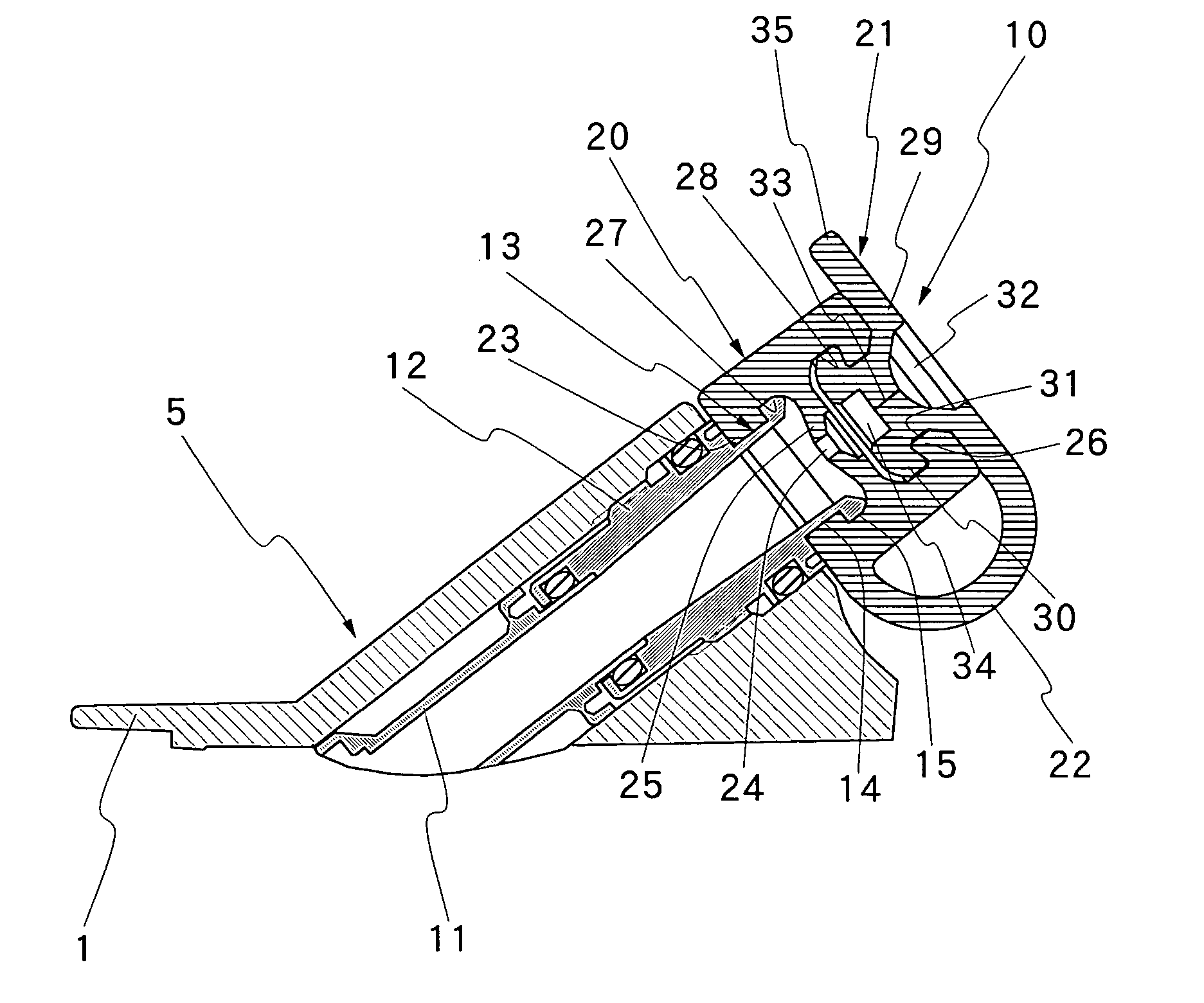
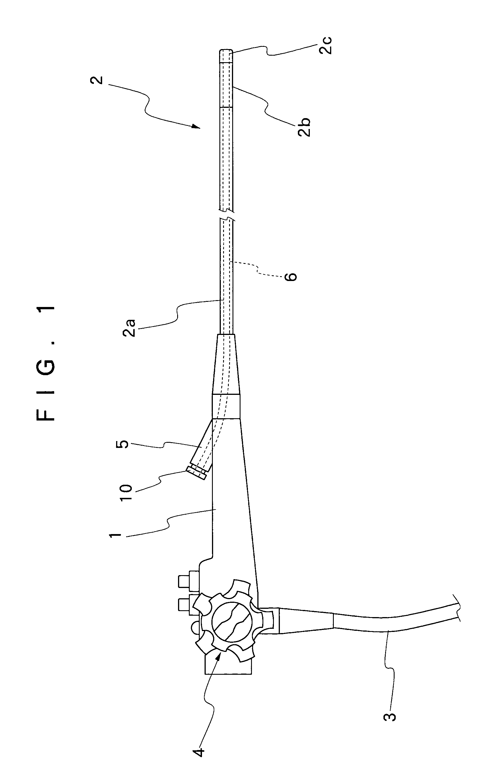
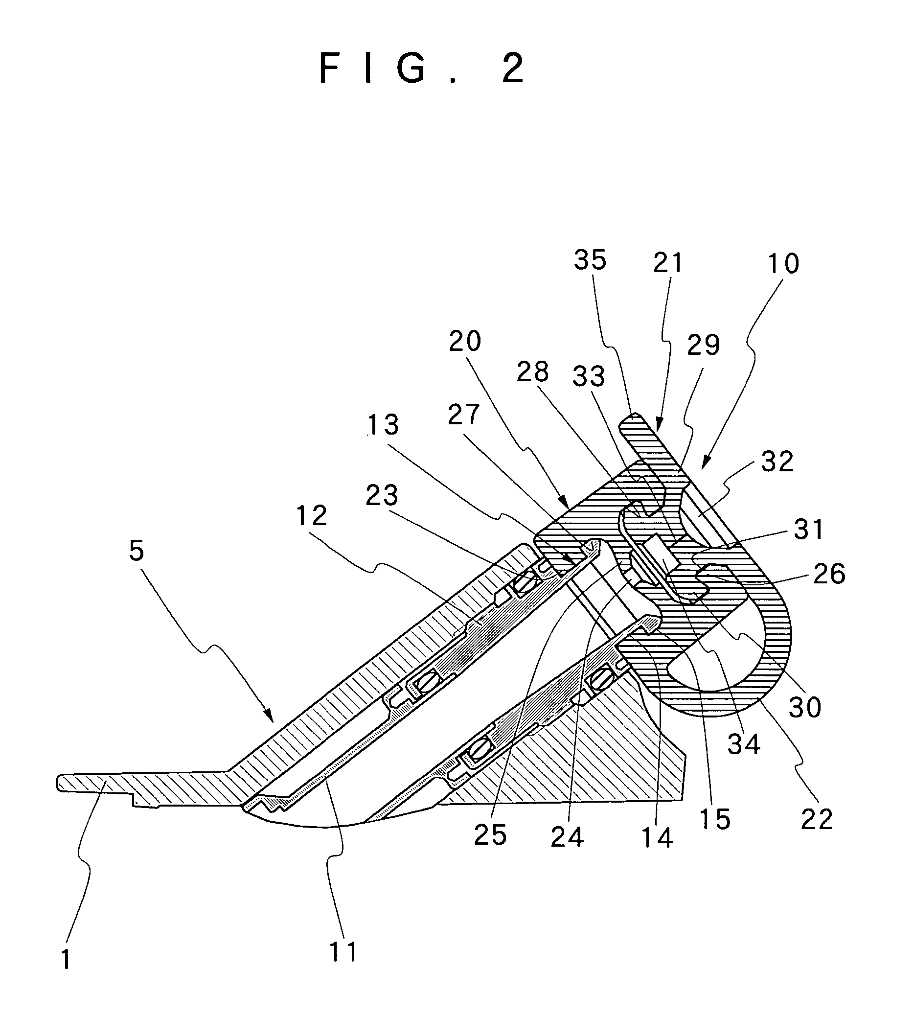
[0032] Hereafter, the present invention is described more particularly by way of its preferred embodiments with reference to the accompanying drawings. Shown in FIG. 1 is the general layout of an endoscope. In that figure, indicated at 1 is a manipulating head assembly of the endoscope, at 2 an elongated insertion tube, and at 3 a universal cable. The insertion tube 2 which is extended out on the front side of the manipulating head assembly 1 is composed of an elongated flexible body 2a which occupies a major portion of the elongated insertion tube 2 and flexibly bendable along bent portions in a path of insertion, a rigid tip end section 2c and an angle section 2b which is connected between a fore distal end of the flexible body portion 2a and the rigid tip end section 2c. Illumination means as well as optical image pickup means of endoscopic observation means (both not shown) are built into a casing of the rigid tip end section 2c of the insertion tube 2. The angle section 2b can ...


PUM


Abstract

A valved plug to be fitted on a mouth piece at an inlet opening of an endoscopic biopsy channel. The plug as a whole is formed of a resilient material, and has, at the opposite ends of a foldable connecting strip or string, a generally tubular main body portion which is provided with a constricted portion in its axial passage, and a valved nesting piece which is adapted to be detachably coupled with the main body portion and provided with a normally closed slit valve axially in an aligned position relative to the constricted passage on the side of the main body portion. The main body portion is provided with an inward interlocking projection of a predetermined thickness at its outer end, for tight interlocking engagement with an interlocking groove which is provided on the side of the nesting piece in such a way as to grip the interlocking projection tightly in a compressed state.

Description

[0001] 1. Field of the Art[0002] This invention relates to a valved plug for an endoscopic biopsy channel, and more particularly to a valved plug to be detachably fitted on a mouth piece at an entrance opening to a biopsy channel, which is provided on medical endoscopes for introduction of forceps or other biopsy and surgical instruments.[0003] 2. Prior Art[0004] Generally, medical endoscopes which are introduced int a body cavity for examination or therapeutic purposes are largely constituted by a manipulating head assembly to be gripped in an operator's hand for manipulating of various control means, an insertion tube extended out on the front side of the manipulating head assembly, and a universal cable which is led out on the rear side of the manipulating head assembly for connection to a light source etc. Along with an endoscopic image pickup means, an illumination window or windows are provided in a casing of a tip end section at the fore distal end of the insertion tube to pr...

Claims


Application Information

Patent Timeline
IPC IPC(8): A61B1/00G02B23/24A61B1/018
CPCA61B1/018A61B1/00137
Inventor AKIBA, HARUO
Owner FUJI PHOTO OPTICAL CO LTD
Why Eureka
Try Eureka