Medical inspection device

a medical inspection and optical diagnostic technology, applied in the field of medical and dental optical diagnostic instruments, can solve the problems of discomfort for patients, and affecting the use of the instrument by users with minimal training,

Inactive Publication Date: 2005-01-13
JORY TSAI
View PDF29 Cites 72 Cited by
  • Summary
  • Abstract
  • Description
  • Claims
  • Application Information

AI Technical Summary

Benefits of technology

[0014] A still further aspect of the invention includes a portable hand-held instrument of the type selected from the group consisting of otoscopes, ophthalmoscopes, larynx scopes, nasopharynx scopes, dermatologic scopes, anoscopes, or veterinary scopes. This instrument includes a body having a pistol-grip adapted for engagement by a user's hand, the body including a speculum disposed thereon. The speculum has a distal opening disposed along an axis of examination, and is sized and shaped to allow location of the distal opening a predetermined distance from a target. A lens and a light outlet are disposed integrally within the body. A video display is disposed within the body, within the axis of examination. A wireless communication module is disposed within the instrument, and is configured to communicate with a remote device. A voice recognition module is also disposed within the instrument to operate the instrument in response to voice commands. A controller disposed within the instrument, with at least one tube extending from the controller to the distal end of the speculum. The tube is configured to communicably couple the controller to an exterior of the speculum at the distal end.

Problems solved by technology

A disadvantage of such devices, however, is that they tend to be awkward to use, as such instruments tend to be difficult for the examining physician to hold, to manipulate and to obtain the necessary views for the examination while simultaneously viewing the image on the remote monitor.
Thus, while many prior art instruments may be designed to facilitate manipulation by the user, the ergonomics of such devices tends to divert the user's attention away from the patient during examination, which may result in discomfort to the patient due to errant manipulation of the instrument.
This drawback may be particularly problematic with respect to new users, or those with minimal training in the use of such instruments.

Method used


Image

  • Medical inspection device
  • Medical inspection device
  • Medical inspection device

Examples


Embodiment Construction

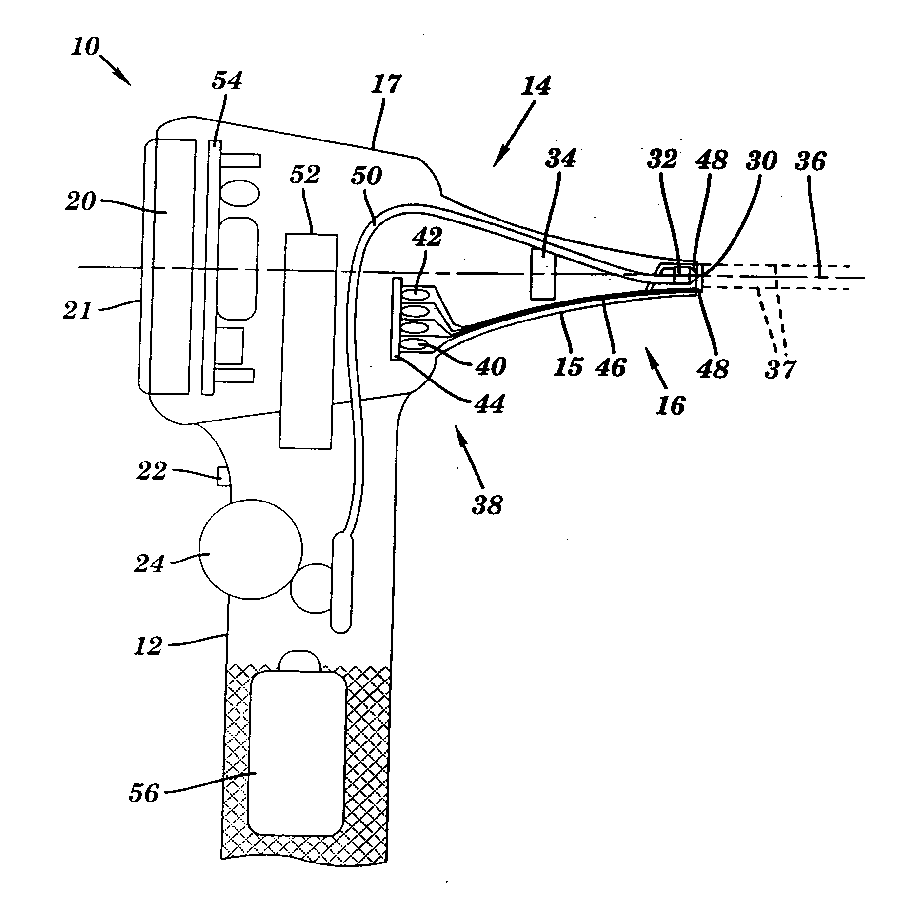
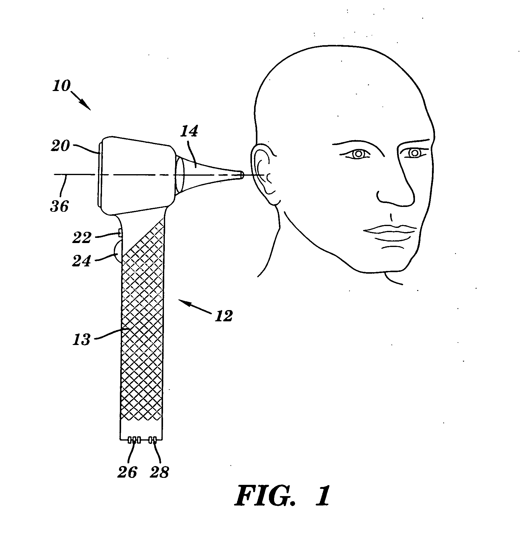
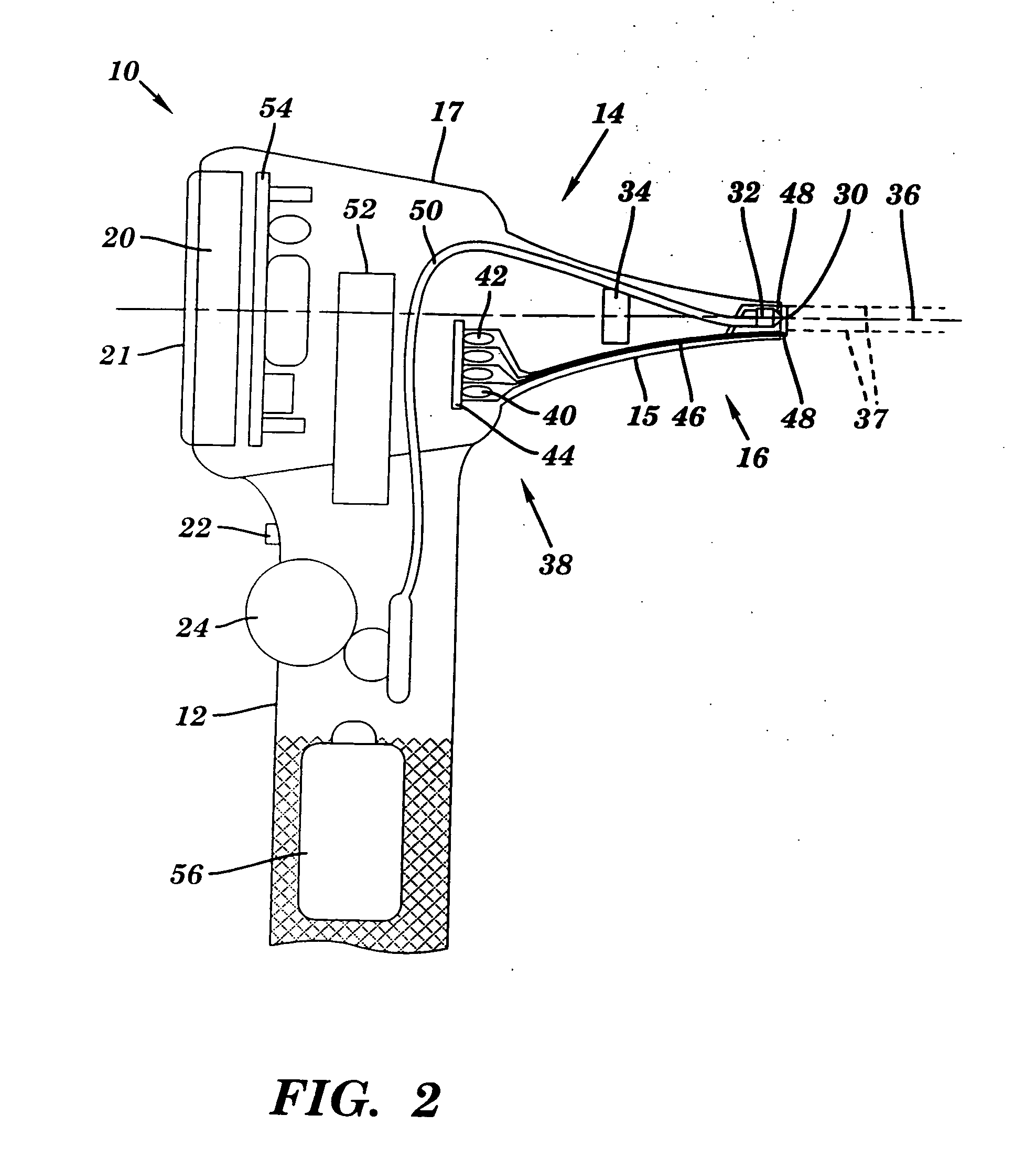
[0026] As shown in FIGS. 1-3, the present invention includes a dental / medical instrument 10 for use in diagnostic and related patient inspection / examination. The device includes a body 12 including an integral speculum 14 with a video image capture device or camera 16, a power supply and a video display 20. These components, in addition to user actuatable controls including a power switch 22 and image focus control 24, are preferably disposed integrally with the body 12. (Portions of the image capture device, such as image sensor 34, as will be discussed hereinbelow, may be disposed remotely from the body 12, and coupled thereto through a port 28.) The body 12 is adapted for convenient engagement and manipulation by a user's hand. The video display is disposed on a display portion of the speculum, while components of the image capture device, such as a lens and light emitter, are disposed on a nose portion of the speculum. As shown in FIGS. 6a-6e, the nose portion is modularly repla...


PUM


Abstract

A dental/medical instrument is provided for use in diagnostic and related patient inspection/examination. The device includes a body having an integral speculum with a video image capture device, a power supply and a display. These components, in addition to user actuatable controls, are disposed integrally with the body. The body is adapted for convenient engagement and manipulation by a user's hand to provide a unitary, hand-held device capable of illuminating and capturing an image of a patient, and displaying the image. Components of the image capture device, such as a lens and light emitter, are disposed on a nose portion of the speculum. The nose portion is modularly replaceable with alternate nose portions sized and shaped to facilitate various discrete medical/dental examination procedures. The instrument also includes a tube and controller configured to apply material, capture data, and/or effect movement of the speculum.

Description

[0001] This application is a Continuation-In-Part of U.S. patent application Ser. No. 09 / 683,253, filed on Dec. 5, 2001, entitled “Medical Inspection Device”, which is a Continuation-In-Part of U.S. patent application Ser. No. 09 / 409,127, now U.S. Pat. No. 6,361,489, filed on Sep. 30, 1999, entitled “Medical Inspection Device”, which is a Continuation-In-Part of U.S. patent application Ser. No. 09 / 199,963, now U.S. Pat. No. 6,186,944, filed on Nov. 25, 1998, entitled “Medical Inspection Device”.BACKGROUND OF THE INVENTION [0002] 1. Field of the Invention [0003] The present invention relates to medical and dental optical diagnostic instruments, and more particularly to an integrated hand held viewing scope and display for use as an otoscope, ophthalmoscope, larynx illumination, nasopharynx illuminator, dermatologic magnifier and anoscope. [0004] 2. Background Information [0005] Various hand held instruments for use by a physician or dentist during examination of a patient have been k...

Claims


Application Information

Patent Timeline
Patent Type & Authority Applications(United States)
IPC IPC(8): A61B1/227A61B1/233A61B1/24A61B1/267
CPCA61B1/00052A61B1/00105A61B1/227A61B1/0607A61B1/24A61B1/267A61B2560/0456A61B1/233
Inventor TSAI, JORY
Owner JORY TSAI
Why Eureka
Try Eureka