Acoustic transducer with mechanical balancing

a transducer and mechanical technology, applied in the field of transducers, can solve the problems of reducing the mass of the cone, limiting the ability of the cone to vibrate at high frequencies, and limiting the ability of the cone to vibrate at high frequencies, and achieve the effect of a wider array of sound waves

Active Publication Date: 2005-02-17
HARMAN INT IND INC
View PDF15 Cites 29 Cited by
  • Summary
  • Abstract
  • Description
  • Claims
  • Application Information

AI Technical Summary

Benefits of technology

[0020] This invention provides a design for a low-profile transducer. The low-profile transducer may be used alone or incorporated with a loudspeaker enclosure including additional transducers to produce a br

Problems solved by technology

Cone-type transducers are typically characterized by a relatively high cone and coil mass, which limits the ability of the cone to vibrate at high frequencies.
Some designs reduce the mass of the cone, but may do so at the cost of rigidity of the cone.
Cones that are less rigid may suffer from distortion caused when a cone flexes instead of imparting pressure to the adjacent air.
Flexing of the cone leads to “break-up”—a failure of the cone to properly reproduce a sound wave.
For example, even though planar transducers can be significantly thinner than

Method used


Image

  • Acoustic transducer with mechanical balancing
  • Acoustic transducer with mechanical balancing
  • Acoustic transducer with mechanical balancing

Examples


first embodiment

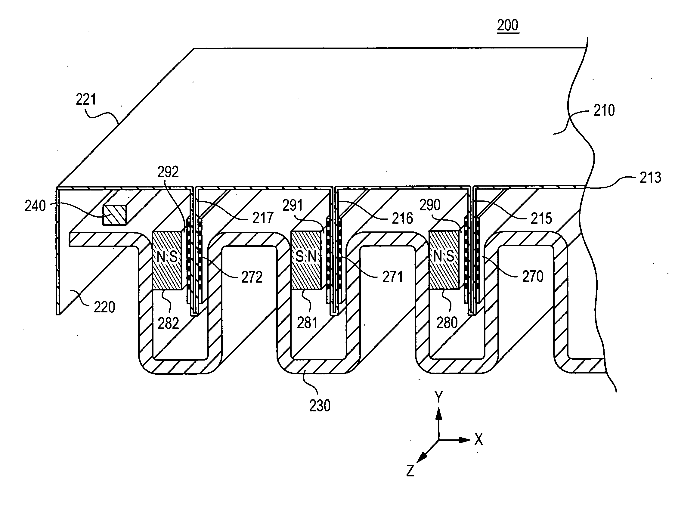
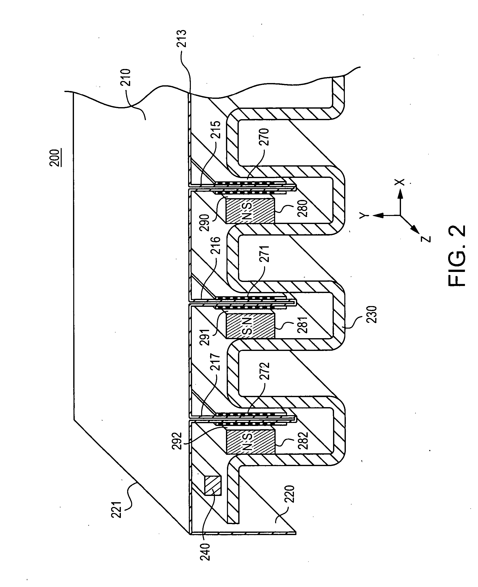
[0044]FIG. 2 is a perspective view of a low-profile transducer 200. The low-profile transducer 200 includes a frame 230; a diaphragm 210 having a perimeter 221, a substantially planar projection surface 213, one or more side surfaces 220, fins 215, 216, and 217 mounted substantially perpendicular to the projection surface 213; stationary magnets 280, 281, and 282, magnetic gaps 290, 291, and 292; voice coils 270, 271, and 272, and a pliable surround 240. The voice coils 270, 271, and 272 are mounted on the fins and reside partially in the magnetic gaps. The low-profile transducer 200 may incorporate these elements in a way that offers the energy efficiency of a cone-type transducer with the reduced depth of a planar transducer. While a particular configuration is shown, the low-profile transducer 200 may have other configurations including those with fewer or additional components.

[0045] The frame 230 may be substantially crenellated or corrugated in shape, as shown. The frame 230 m...

second embodiment

[0065]FIG. 8 is a cross-sectional view of a low-profile transducer 800. The low-profile transducer 800 includes a crenellated ferromagnetic frame 830, a rigid diaphragm 810 having a substantially planar projection surface 813, stationary magnets 880, magnetic gaps 890; voice coils 870; and a pliable surround 840. The diaphragm 810 is made of a substantially rigid material, with voice coils 870 mounted onto the diaphragm and extending away from the diaphragm. The voice coils 870 are preferably mounted in a direction extending perpendicularly away from the surface of the diaphragm 810, and reside partially in the magnetic gaps 890 formed by the magnets 880 and the frame 830. The stationary magnets 880 are attached to a portion of the frame 830 extending in the z-direction, with poles aligned in the x-direction, parallel to the plane of the substantially planar projection surface 813. The magnetic gaps 890 may be formed adjacent to poles of the stationary magnets 880. The magnets may b...

third embodiment

[0067]FIG. 9 is a cross-sectional view of a low-profile transducer 900. The low-profile transducer 900 includes a crenellated non-ferromagnetic frame 930, a rigid diaphragm 910, stationary magnets 983, 985, 987, and 989, magnetic gaps 990, voice coils 970, and a pliable surround 940.

[0068] The bottom of the frame may have one or more grooves 937 and sides 935. The diaphragm 910 may be made of a substantially rigid material, with voice coils 970 mounted onto the diaphragm and extending away from the diaphragm. The diaphragm may be operatively attached to sides 935 of the frame by the pliable surround 940.

[0069] The low-profile transducer shown in FIG. 9 uses grooves 937 as a technique for extending a range of motion of the voice coils 970. Grooves 937 may be used in a variety of embodiments of a low-profile transducer to accommodate the excursion of the voice coils.

[0070] At least two stationary magnets 987 and 989 are used to form the magnetic gaps 990 between closely-spaced oppos...


PUM


Abstract

One embodiment of a low-profile transducer includes a at least one fin perpendicularly mounted on a planar diaphragm, with a voice coil mounted onto the fin. The voice coil may reside in a strong uniform magnetic field. The locations at which the diaphragm is connected to a frame may be coplanar with a center of mass of the diaphragm. The three-dimensional structure of diaphragm and fins may be formed using origami techniques.

Description

PRIORITY CLAIM [0001] This application claims the benefit of U.S. Provisional Application No. 60 / 461,809, filed Apr. 9, 2003, the disclosure of which is hereby incorporated by reference herein in its entirety. RELATED APPLICATIONS [0002] This application is related to U.S. application Ser. No. ______, filed on Apr. 9, 2004, titled “LOW-PROFILE TRANSDUCER” (Atty. Ref. 11336 / 519 (P03034US)), by inventors An Duc Nguyen and Charles M. Sprinkle, and to U.S. Application Ser. No. ______, filed on Apr. 9, 2004, titled “ACOUSTIC TRANSDUCER WITH FOLDED DIAPHRAGM” (Atty. Ref. 11336 / 713 (P03034USU1) ), by inventors An Duc Nguyen and Charles M. Sprinkle, each of which is incorporated by reference herein in its entirety.BACKGROUND OF THE INVENTION [0003] 1. Technical Field [0004] The invention generally relates to transducers. More particularly, the invention relates to an audio transducer capable of reproducing a sound wave and having the benefits of planar and cone-type transducers. [0005] 2. R...

Claims


Application Information

Patent Timeline
IPC IPC(8): H04R1/00H04R1/24H04R7/04H04R7/12H04R9/06H04R11/02H04R31/00
CPCH04R1/24H04R7/045H04R7/127H04R2307/201H04R31/003H04R2207/021H04R9/063
Inventor NGUYEN, AN DUCSPRINKLE, CHARLES M.
Owner HARMAN INT IND INC
Why Eureka
Try Eureka