Image reading apparatus and image reading method

Inactive Publication Date: 2005-03-03
KK TOSHIBA +1
View PDF3 Cites 0 Cited by
  • Summary
  • Abstract
  • Description
  • Claims
  • Application Information

AI Technical Summary

Benefits of technology

[0013] The object of the present invention is to provide an image reading apparatus and an image reading method wherein when a microstep driving contr

Problems solved by technology

A vibration due to the torque variation may affect the carriage and degrade the quality of the read image.
However, where the rotation speed of the motor varies in accordance with the read magnification, the motor is dri

Method used


Image

  • Image reading apparatus and image reading method
  • Image reading apparatus and image reading method
  • Image reading apparatus and image reading method

Examples


Embodiment Construction

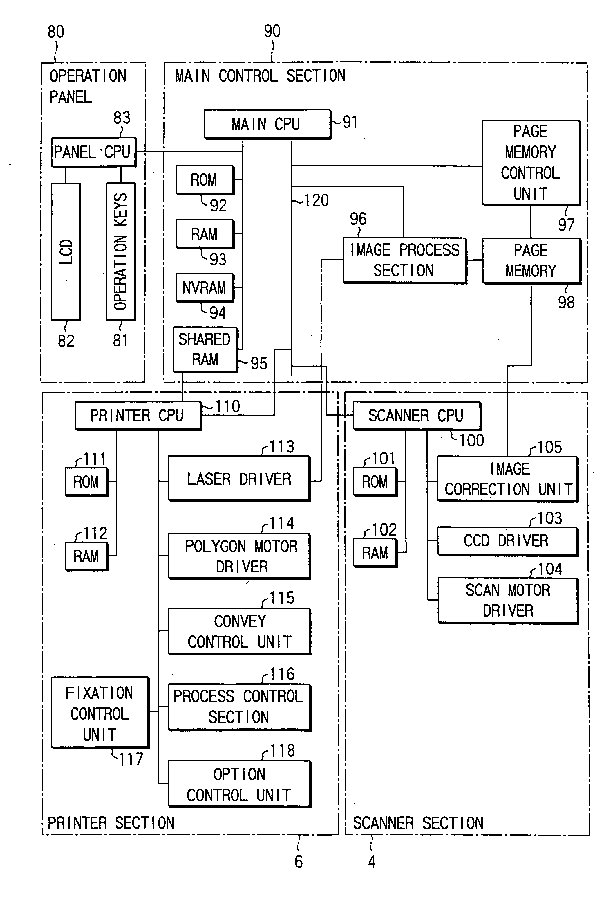
[0030] An embodiment of the present invention will now be described with reference to the accompanying drawings.

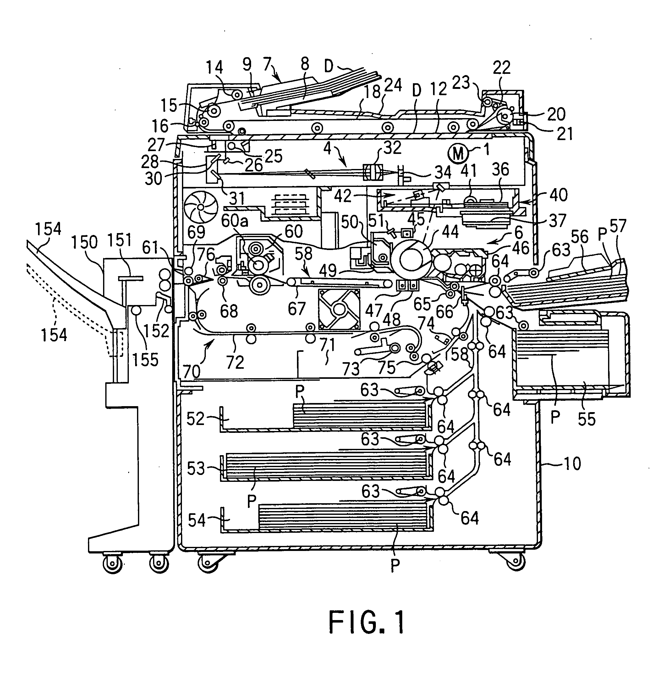
[0031]FIG. 1 shows an internal structure of a digital copying machine having a scanner section as an image reading apparatus according to the present invention.

[0032] In FIG. 1, reference numeral 10 denotes an apparatus main body. The apparatus main body 10 incorporates a scanner section 4 functioning as an image reading apparatus, a printer section 6 functioning as an image output means, and a finished 150 as an option.

[0033] An original table 12 formed of transparent glass, on which a read object, i.e. an original D is placed, is disposed on the upper surface of the apparatus main body 10. An automatic document feeder 7 (hereinafter referred to as “ADF”) for automatically feeding originals D onto the original table 12 is disposed on the upper surface of the apparatus main body 10. The ADF 7 is disposed to be opened / closed with respect to the original table 12 and serv...


PUM


Abstract

Where a magnification (enlargement/reduction of image) has been set through operation keys of an operation panel, a main CPU sends information on read magnification to a scanner CPU of a scanner section. In this case, where the magnification is not set in particular, information of 100% magnification is sent to the scanner CPU. Based on a microstep division number of a step angle corresponding to the received information on read magnification, the scanner CPU controls the driving of a scan motor via a scan motor driver.

Description

[0001] The present application is a continuation of U.S. application Ser. No. 09 / 708,438, filed Nov. 9, 2000, the entire contents of which are incorporated herein by reference.BACKGROUND OF THE INVENTION [0002] The present invention relates to an image reading apparatus, such as a scanner, for optically reading an original by driving a scanning optical system using a pulse-controlled motor. [0003] There is known an image reading apparatus, such as a scanner section of a copying machine or a scanner, for optically reading an original by driving a scanning optical system using a pulse-controlled motor, such as a stepping motor or an encoder-equipped DC servomotor, whose rotation amount or rotation speed can be controlled by a pulse number or a pulse cycle. [0004] In the image reading apparatus for optically reading an original by driving a scanning optical system using a pulse-controlled motor, the pulse (stepping) motor is controlled at the time of reading / scanning in a microstep dri...

Claims


Application Information

Patent Timeline
IPC IPC(8): G06F15/00G06K9/32G06T1/00H04N1/04H04N1/36H04N1/393
CPCH04N1/0402H04N1/0414H04N2201/0081H04N1/1013H04N1/193H04N1/0443
Inventor HASHIZUME, YUSUKE
Owner KK TOSHIBA
Why Eureka
Try Eureka