Terminal assembly for a coaxial cable

a technology of coaxial cable and terminal, which is applied in the direction of electrically conductive connections, coupling device connections, electrical apparatus, etc., can solve the problems of significant manual manipulation, laborious and sensitive techniques, and known methods for assembling terminals to coaxial cables

Inactive Publication Date: 2005-03-10
DELPHI TECH INC
View PDF8 Cites 50 Cited by
  • Summary
  • Abstract
  • Description
  • Claims
  • Application Information

AI Technical Summary

Benefits of technology

[0011] According to a preferred embodiment of the present invention disclosed herein, a terminal assembly for a coaxial cable is provided which includes a ground shield with surfaces defining an internal passageway. In the preferred embodiment, the ground shield includes a strain relief portio

Problems solved by technology

RF leakage results from radiation loss through holes or seams in the terminal or cable.
Such known methods for assembling a terminal to a coaxial cable are labor intensive and technique sensitive.
These methods require significant manual manipulation of the shielding braid which deforms the outer conductor causing reflection and insertion loss.

Method used


Image

  • Terminal assembly for a coaxial cable
  • Terminal assembly for a coaxial cable
  • Terminal assembly for a coaxial cable

Examples


Embodiment Construction

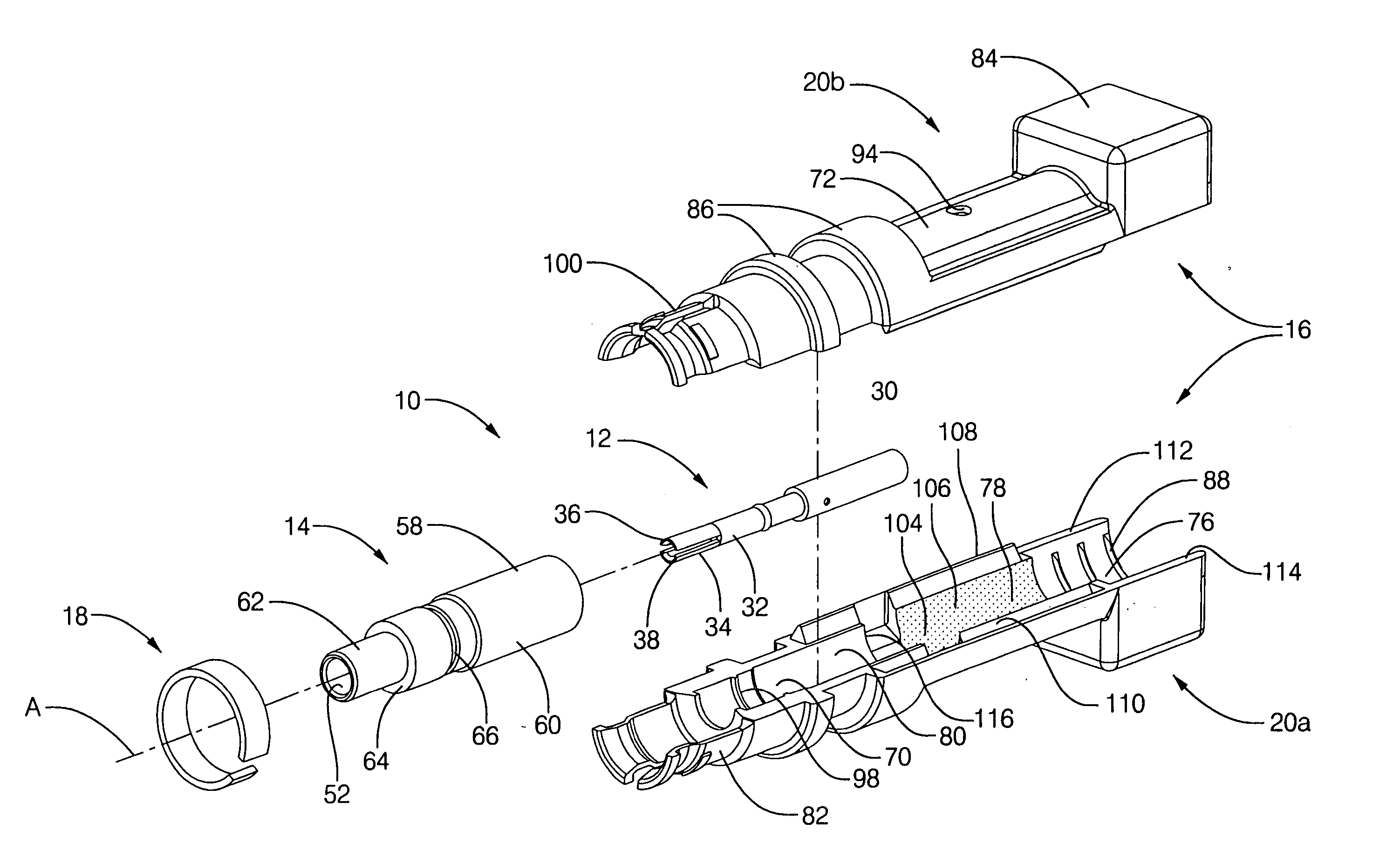
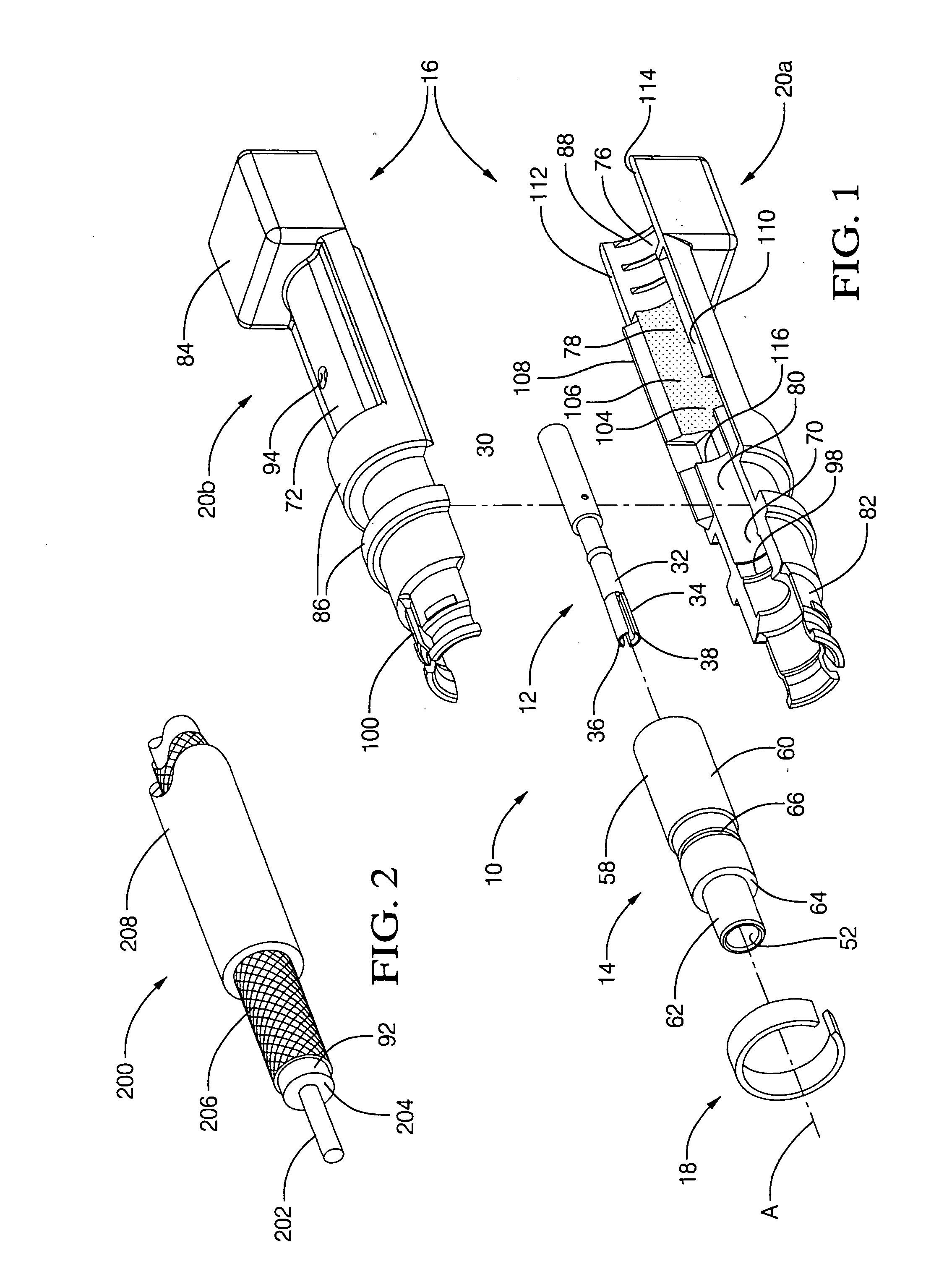
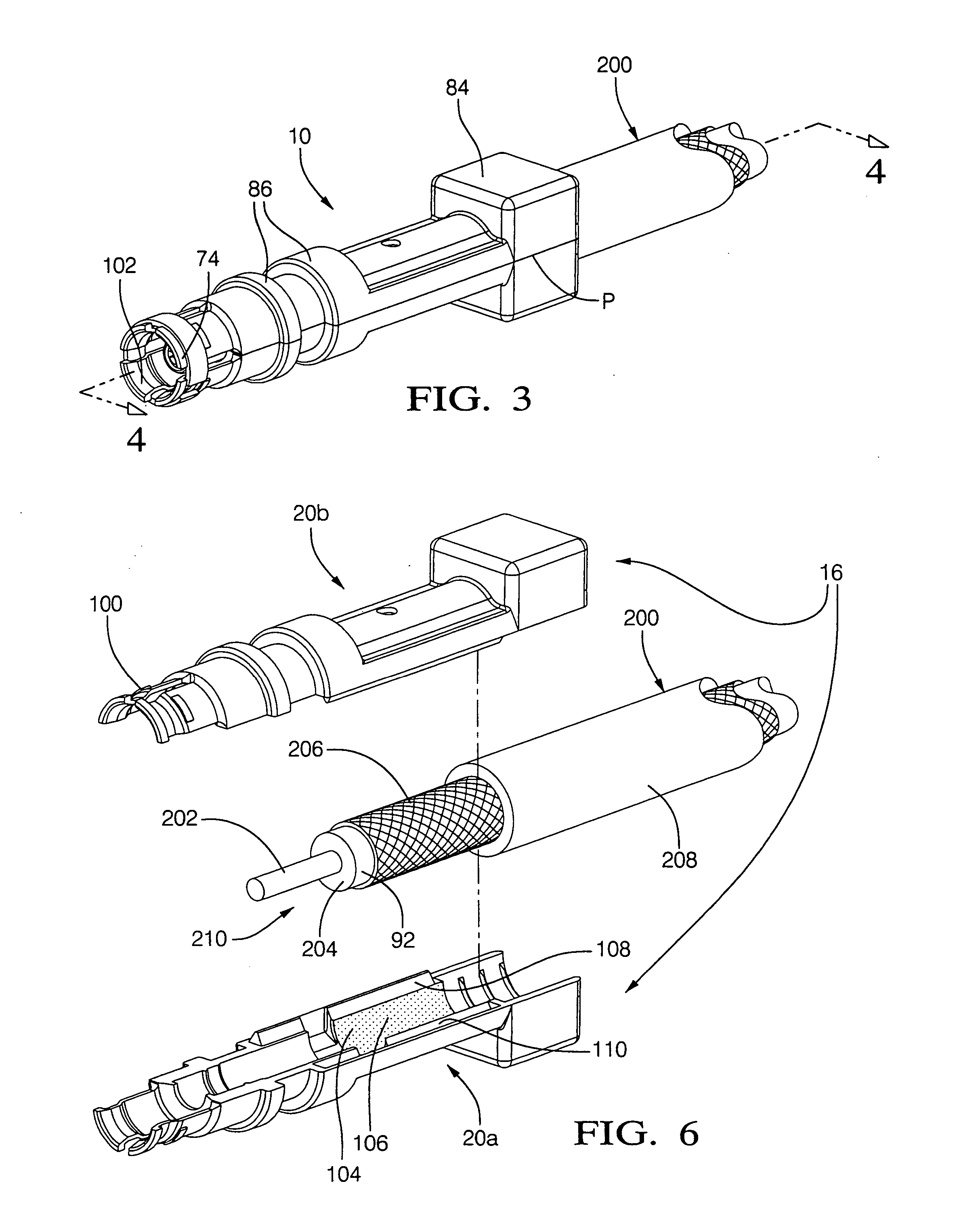
[0022] Referring to the figures wherein like numerals refer to like elements throughout the several views, FIGS. 1, 3, and 4 illustrate a preferred embodiment of an electrical terminal 10 of the present invention. The terminal 10 includes an electrically conductive core conductor 12, a dielectric member 14, a conductive ground shield 16, and a split ring support 18. The ground shield 16 is an assembly of two identical ground shield halves or housing members 20a, 20b. When joined, the ground shield housing members 20a, 20b define the completed ground shield 16. Each ground shield housing member 20a, 20b is preferably a rigid die cast member constructed of a nickel plated zinc alloy.

[0023]FIG. 2 illustrates a coaxial cable 200 which includes an inner conductor 202, an inner dielectric sheath 204 around the inner conductor 202, an outer conductor layer 206 having a cylindrical outer surface and concentrically surrounding the inner dielectric sheath 204 and the inner conductor 202, and...


PUM


Abstract

A terminal for a coaxial cable includes an electrically conductive core mounted in a dielectric member. The dielectric member along with the conductive core are positioned within an electrically conductive ground shield. The ground shield includes two identical split-barrel housing members which are joined together. When joined, the housing members form a cylindrical channel having surfaces which intimately contact an exposed length of cable outer conductor layer, creating a conductive connection between the outer conductor layer and the ground shield and structurally maintaining the outer conductor layer concentric to the dielectric sheath and inner conductor of the cable.

Description

TECHNICAL FIELD [0001] The present invention relates to electrical terminals for connection to coaxial cable and more particularly relates to a terminal having a two-piece ground shield. BACKGROUND OF THE INVENTION [0002] A typical coaxial cable for signal transmission includes a center conductive core or inner conductor surrounded by an inner dielectric sheath. An outer conductor or conductive shield surrounds the inner dielectric sheath and typically is a metal braid. The conductive shield is surrounded by an outer dielectric sheath of the cable. [0003] Electrical terminals are known for terminating a coaxial cable so that the cable can be connected to another connecting device, such as a complementary mating connector, a printed circuit board, and the like. Such terminals typically include a core conductor or contact for mechanically and electrically connecting to an end of the inner conductor of the cable, a dielectric sleeve therearound, and an outer conductor or ground shield ...

Claims


Application Information

Patent Timeline
IPC IPC(8): H01R4/02H01R9/05H01R13/504H02G15/08
CPCH01R4/023H02G15/085H01R13/5045H01R9/0524
Inventor GLADD, JOSEPH HOWARDHICKOX, JEFFREY MICHAELKETTERER, WILLIAM C.
Owner DELPHI TECH INC
Why Eureka
Try Eureka