Stand mixer

Inactive Publication Date: 2005-03-17
VIKING RANGE
View PDF16 Cites 41 Cited by
  • Summary
  • Abstract
  • Description
  • Claims
  • Application Information

AI Technical Summary

Benefits of technology

[0006] To these ends, the stand mixer described herein includes feet upon which the mixing apparatus securely rests during operation or when idle. In order to make the stand mixer easy to move, wheels have been included on the base of the machine. Since the wheels are typically not in contact with the surface when the stand mixer is in use o

Problems solved by technology

Prior mixing devices have failed to provide an easily maneuverable mixer that rests on a stable base while in use or while idle, but that can be easily moved into a desired position through the engagement of wheels attached to the

Method used


Image

  • Stand mixer
  • Stand mixer
  • Stand mixer

Examples


Example

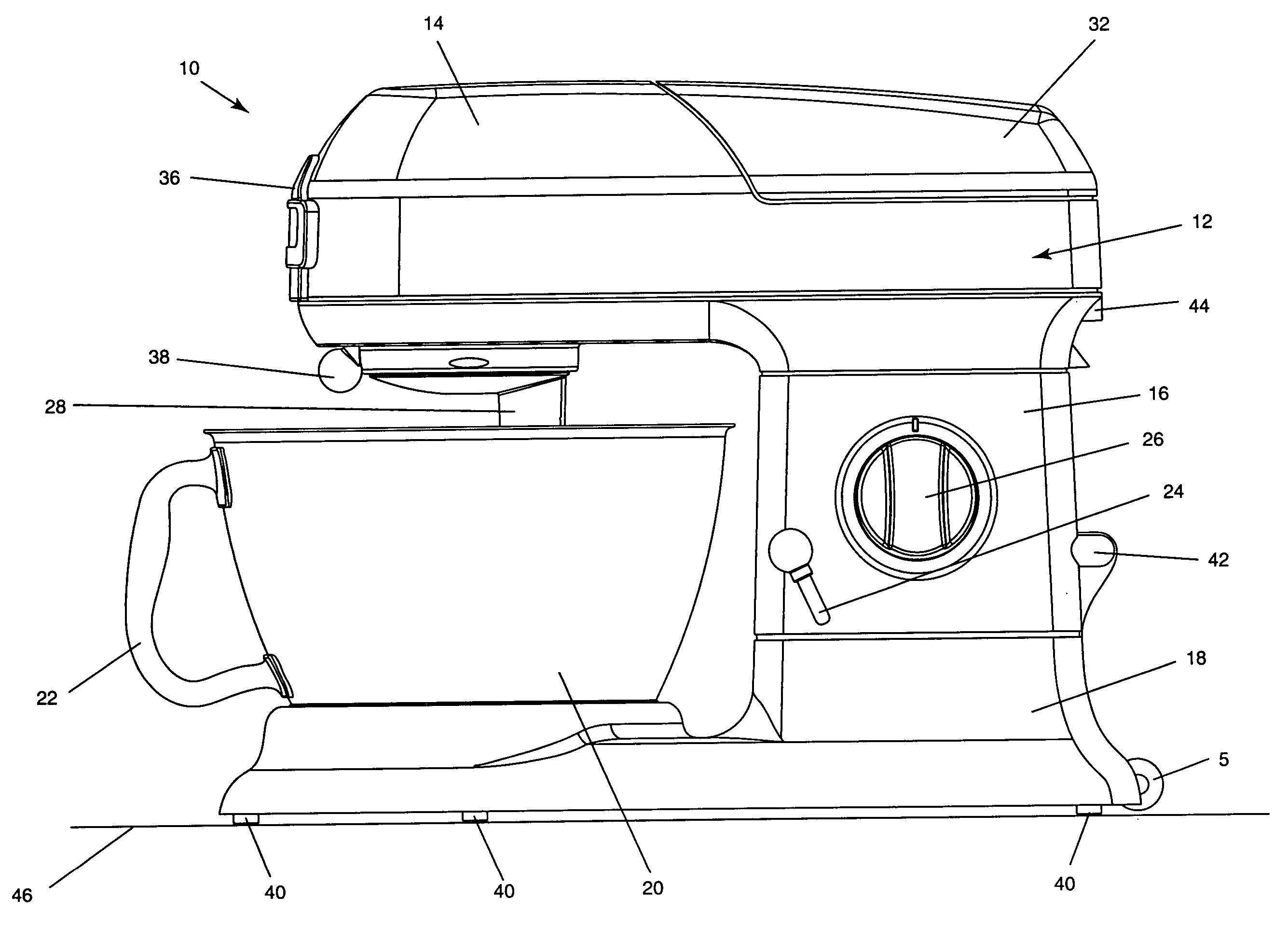
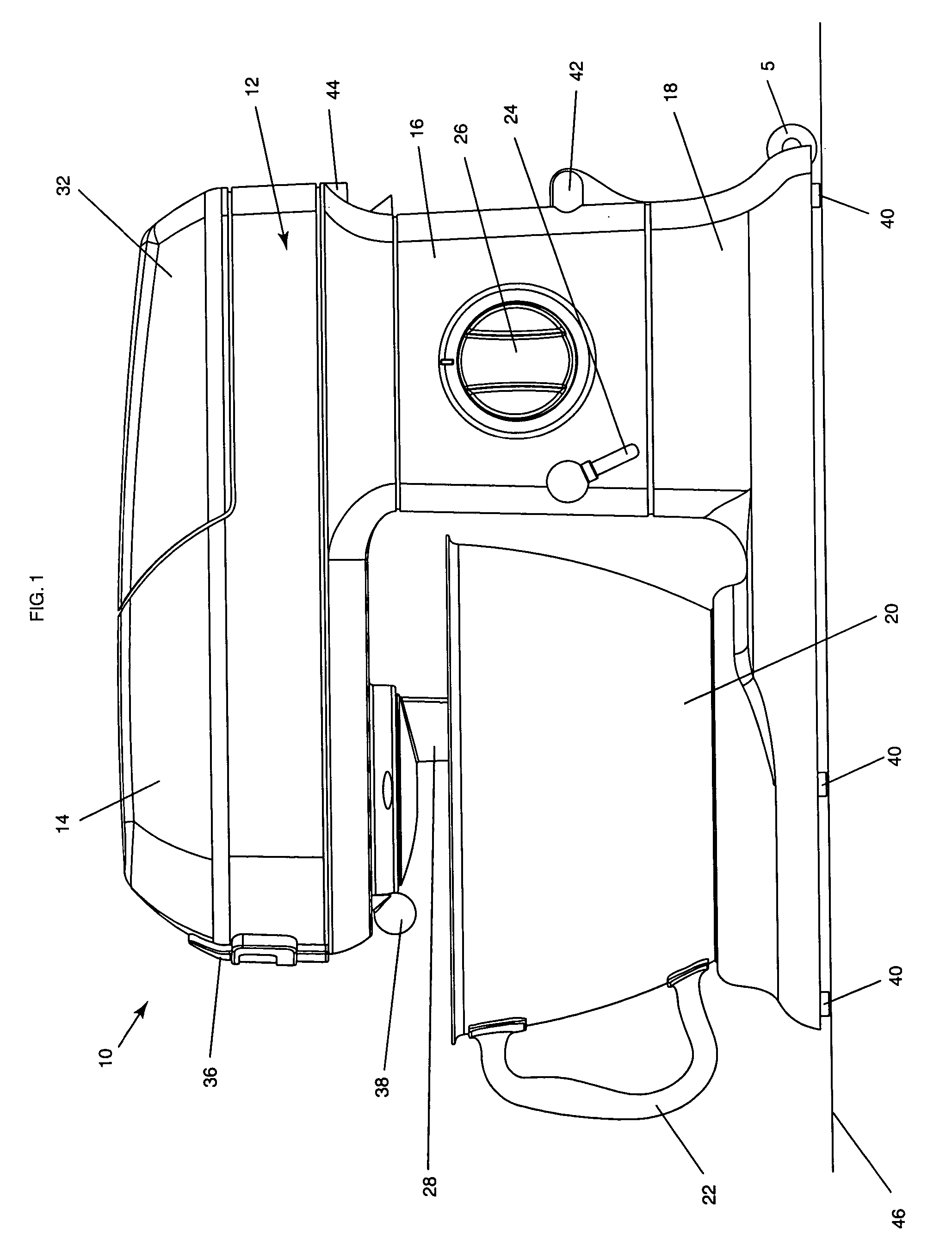
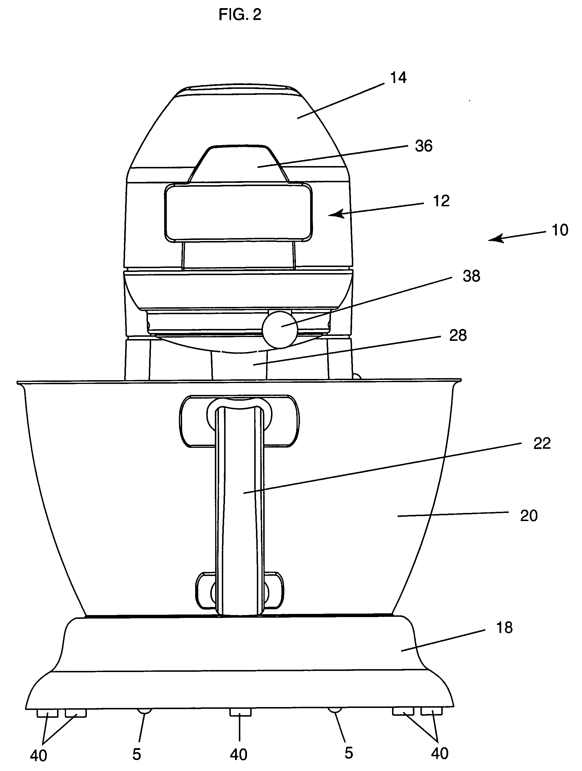
[0017]FIGS. 1-5 show various views of a stand mixer 10. The stand mixer 10 includes a body 12, a head 14, a motor housing 16, and a base 18. The stand mixer 10 rests on a surface 46 as shown in FIG. 1. Although the various elements of the body 12 could be formed as an integral unit, typically, the head 14, motor housing 16, and base 18 are separately formed and are securely affixed together. The base 18 can receive and house a bowl 20 with a handle 22 disposed thereon. The bowl 20 and handle 22 are typically formed of stainless steel, but could be formed of any other durable alternative. The handle 22 of the bowl 20 can be integrally formed as a part of the bowl or can be formed separately and affixed securely thereto through welding or any other method that would ensure a secure attachment. The bowl 20 is attached to the base 18 by placing the bowl 20 into the pre-cut slots and turning the bowl 20 clockwise to lock into the base 18. When the bowl 20 is in the locked position, the h...


PUM


Abstract

A stand mixer is provided with wheels proximate the base. The base houses a mixing bowl capable of being placed into a locked position. When the mixing bowl is in the locked position, its handle faces outward. The mixer can be lifted with the handle to transfer the weight of the stand mixer from the feet to the wheels. The stand mixer can then be moved into a desired position.

Description

FIELD OF THE INVENTION [0001] This invention relates to a stand mixer that can be moved by pivoting the base onto attached wheels by lifting a handle. BACKGROUND OF THE INVENTION [0002] Several types of mixers exist in the prior art that range from materials mixers, such as cement mixers, to food mixers. [0003] Prior mixing devices have failed to provide an easily maneuverable mixer that rests on a stable base while in use or while idle, but that can be easily moved into a desired position through the engagement of wheels attached to the base. The prior art also fails to disclose a mixing apparatus that can be moved using a handle that has been locked into a secure position to allow a user to pivot the stand mixer onto the wheels for movement to a desired location. SUMMARY OF THE INVENTION [0004] This invention relates to a stand mixer with a base that houses a mixing bowl with a handle, that rests on feet, and that has wheels attached at a rear portion. The handle can be lifted to ...

Claims


Application Information

Patent Timeline
IPC IPC(8): A47J43/044A47J43/07B01F7/16
CPCA47J43/044B01F7/1605A47J2043/04454A47J43/0705B01F27/805
Inventor HOOPER, RYANBAILEY, BRENT
Owner VIKING RANGE
Why Eureka
Try Eureka