Method and device for cooling beverages

Inactive Publication Date: 2010-01-07
TIRBICOOL SPRL
View PDF15 Cites 7 Cited by
  • Summary
  • Abstract
  • Description
  • Claims
  • Application Information

AI Technical Summary

Benefits of technology

[0012]In particular, another object of the invention is to provide a beverage dispenser that enables a beverage source to be cooled continuously and instantaneously, including when the barrel containing a beverage is at a high temperature without any intermediary between the refrigerant and the beverage duct. Yet another object of the invention is to provide a beverage dispenser enabli

Problems solved by technology

If the coil or the tank is immersed in an ice bath, the main drawbacks that may be observed are the low efficiency of heat transfer to the ice and its cost, and also the difficulty of obtaining and transporting blocks of ice of limited longevity.
If the coil or the tank is immersed in a water bath refrigerated by a conventional refrigerating unit, the main drawbacks of such an apparatus that may be observed are the need to have a tank of large size in order to contain the refrigerated water, the long time to fill the tank with water, (which is not easy for dispensing in “flying pump” mode) and the time to cool the volume of water and therefore the considerable delay between starting the apparatus and dispensing the first cooled beverage.
In this regard, the reader may refer to U.S. Pat. No. 3,712,514, the main drawbacks of which are the time to cool the tank, which must be entirely cooled before dispensing, the large dimensions of the lagged chamber containing the tank and evaporator, and the presence of air (with a very low thermal exchange coefficient) between the tank and the evaporator.
However, this system has

Method used


Image

  • Method and device for cooling beverages
  • Method and device for cooling beverages
  • Method and device for cooling beverages

Examples


Example

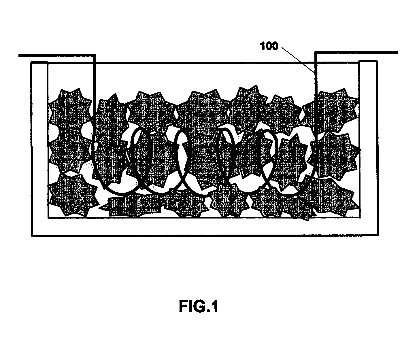
[0038]FIG. 1 is a simplified view of a beverage cooling device of the prior art in which a line 100 (for example a coil) transporting a beverage is immersed in a water bath containing ice.

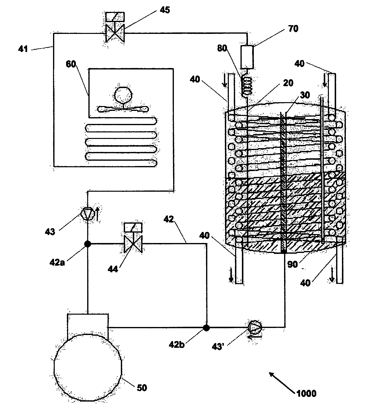
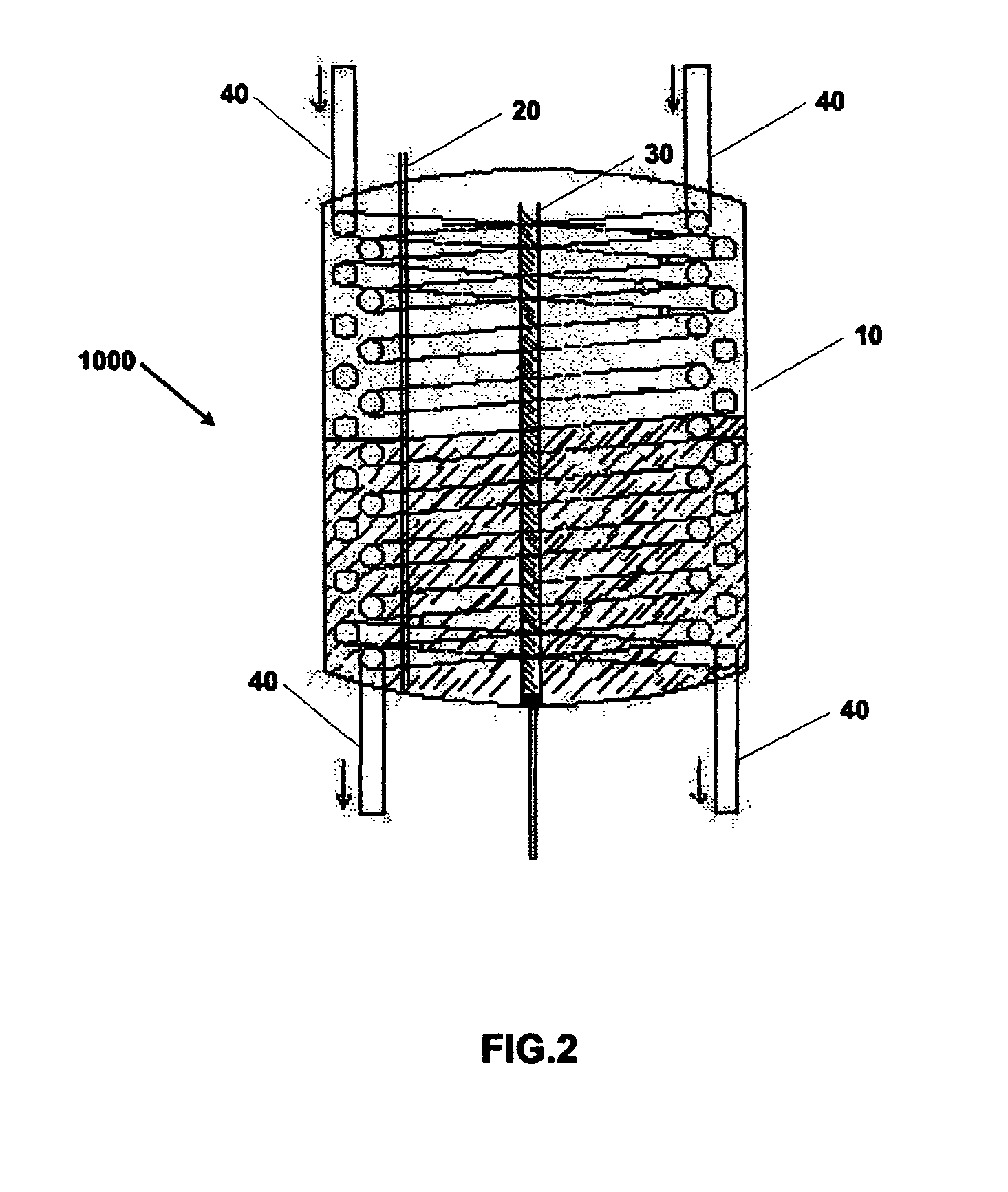
[0039]FIG. 2 is a diagram showing the general principle of one operating mode of a beverage dispenser according to the invention. The dispenser 1000 comprises:[0040]a source of refrigerant (such as a conventional refrigerating circuit using for example R22, R404 or R407, or a liquefied gas cylinder containing for example CO2, etc . . . );[0041]a lagged tank 10, in the form of cylinder 28 cm in diameter and 40 cm in height made of sheet metal 4 mm in thickness designed to contain said refrigerant in the liquid form in its lower part and to allow said refrigerant to evaporate, and designed to contain the refrigerant in gaseous form in its upper part;[0042]a first line 20 for transporting the refrigerant in liquid form in the lower part of the tank 10;[0043]a second line 30 designed to withdraw the re...


PUM


Abstract

The invention relates to a beverage dispenser (1000) for dispensing beverages, that comprises: a refrigeration circuit (41); a tank (10) for containing said coolant at a liquid state coming from a first duct (20) in the lower portion thereof and evaporating said coolant into a gaseous state, and for containing said coolant in a gaseous state in the upper portion thereof; a second duct (30) for collecting the coolant at the gaseous state from said tank (10); at least one duct (40) for circulating said beverage to be dispensed inside said tank (10) and according to a thermal exchange relation with the coolant at the liquid and/or gaseous state.

Description

SUBJECT OF THE INVENTION[0001]The present invention relates to a device and a method for cooling and dispensing beverages. In particular, the invention relates to a device and to a method for cooling and dispensing beer and other beverages in “flying pump” mode.TECHNOLOGICAL BACKGROUND[0002]Systems designed to dispense beverages, such as beer, sparkling wines, sodas, etc., while maintaining the beverages at a given temperature, which may vary from one beverage to another, have been known for a long time. In the case of beer for example, it is known that it freezes below a temperature of −1.5° C. and foams above 4° C., and that the tasting temperature depends on the type of beer (and therefore, depending on the type of beer, the temperature allows the beverage to reveal its taste, flavor and aroma). Typically, two methods are known for cooling beverages.[0003]The first method is that in which a coil or a tank containing a beverage is immersed either in an ice bath or in a water bath ...

Claims


Application Information

Patent Timeline
IPC IPC(8): F25B49/00F25D13/00
CPCB67D1/0859F25B39/00F25D31/002F25B2400/0401F25B2339/0242B67D1/08F25D31/00
Inventor THIRY, JOSE
Owner TIRBICOOL SPRL
Why Eureka
Try Eureka