Multifunction fluid connector for automotive vehicle power system

Inactive Publication Date: 2010-09-09
FORD GLOBAL TECH LLC
View PDF12 Cites 10 Cited by
  • Summary
  • Abstract
  • Description
  • Claims
  • Application Information

AI Technical Summary

Benefits of technology

[0013]It is an advantage of a multifunction fluid conductor according to the present invention that the number of different, unique, components required for service or to be fitted as original equipment on a line of vehicles may be reduced because certain devices such as a PCV fitting, an EGR valve, or manifold pressure sensor or other devices may be added without the necessity of additional hardware, and without providing additional fittings to an engine part such as an intake manifold or transmission case.
[0014]It is another advantage of a mult

Problems solved by technology

As a result, added expense is frequently incurred for providing fittings, for example for an EGR valve o

Method used


Image

  • Multifunction fluid connector for automotive vehicle power system
  • Multifunction fluid connector for automotive vehicle power system
  • Multifunction fluid connector for automotive vehicle power system

Examples


Embodiment Construction

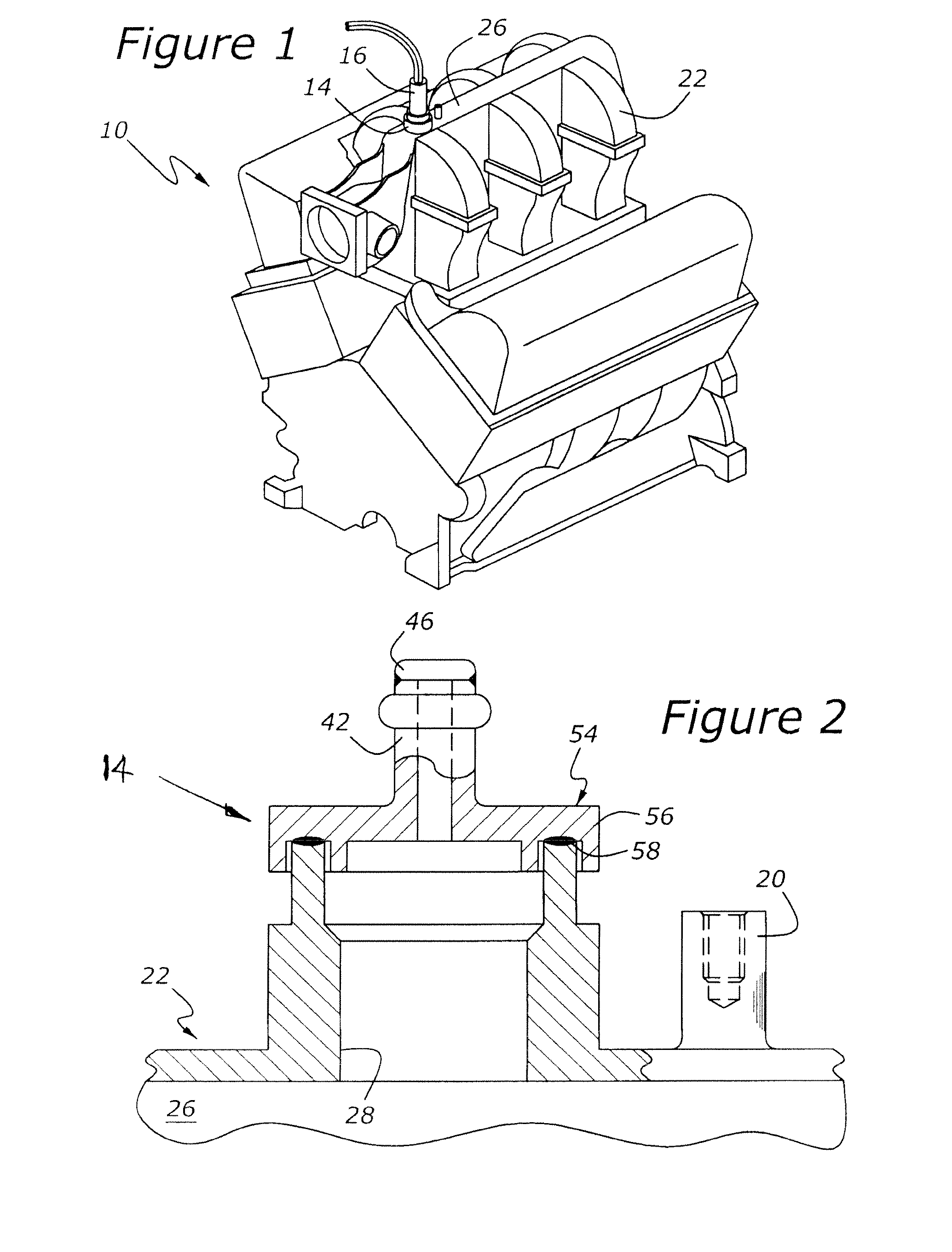
[0023]According to an aspect of the present invention shown in FIG. 1, engine 10 has an intake manifold, 22, with a multifunction fluid connector, 14, incorporated therein. A manifold absolute pressure sensor, 16, is mounted to multifunction fluid connector 14. Sensor 16 generates a signal related to the pressure of induction air flowing within manifold 22. This signal is communicated to an engine controller (not shown).

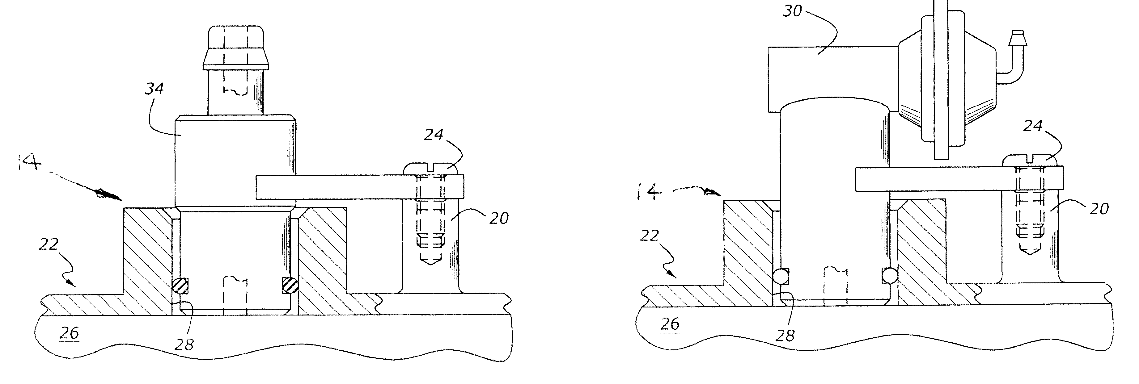
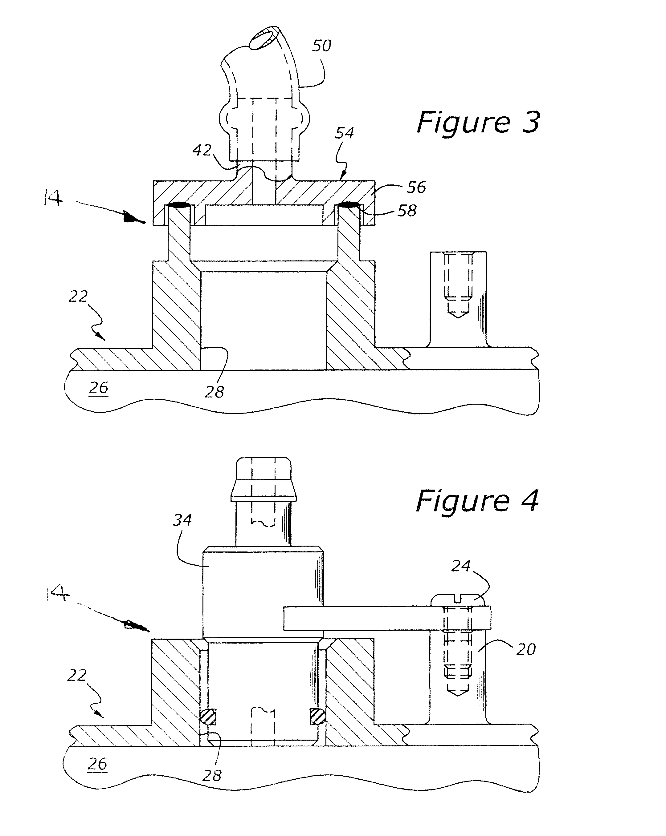
[0024]FIG. 2 is a sectional view showing multifunction fluid connector 14 as being mounted to an intake plenum, 26, of intake manifold 22. Intake plenum 26 has a bore, 28, which is closed by multifunction fluid connector 14. More specifically, multifunction fluid connector 14 has a generally tubular first portion, 42, having a closed end, 46. Tube 42 is attached to a second portion, 54, which is a foundation structure having a flanged end, 56, which is attached to the wall of bore 22 by means of a weld bead, 58. The welding may be accomplished by friction welding, so...


PUM


Abstract

A multifunction fluid connector for an automotive vehicle power system includes a base component having at least one passage for conducting a fluid, with the passage ending in a bore which is closed by a multifunction fluid connector having three functional states in which the connector is either closed, or open to allow attachment of a hose or other conductor in fluid communication with the passage through the base component. In a final state, a fluid handling device such as a PCV valve, a MAP sensor, an EGR valve or other type of fluid handling component may be situated within the bore of the base component.

Description

CROSS REFERENCE TO RELATED APPLICATIONS[0001]None.BACKGROUND OF THE INVENTION[0002]1. Field of the Invention[0003]The present invention relates to a fluid connector having a number of different operating modes rendering the connector particularly useful for automotive vehicle powertrain elements.[0004]2. Related Art[0005]Automotive designers strive to maintain the highest practicable degree of commonality between components used for various vehicular powertrains. For example, an engine intake manifold is expensive to tool and produce, and, as a result, it is desirable to provide a manifold having a design which is suitable for use in several different vehicles. However, tuning of engines and powertrains for different vehicles sometimes requires modifications to the equipment of the engine. For example, oftentimes it is necessary to utilize an exhaust gas recirculation (EGR) valve and sometimes it is not. And, it is desirable to avoid using costly componentry where it is not necessar...

Claims


Application Information

Patent Timeline
IPC IPC(8): F16L41/00
CPCF02M35/10222F02M35/1036F16L41/086F02M35/116F16L41/084F02M35/1038
Inventor NEWMAN, CHRISTOPHER WILLIAMKOSKO, JEFF RICHARDWAGNER, TERRANCE
Owner FORD GLOBAL TECH LLC
Why Eureka
Try Eureka