
Device and method for determining analyte levels

Inactive Publication Date: 2012-07-12
DEXCOM
View PDF2 Cites 103 Cited by
  • Summary
  • Abstract
  • Description
  • Claims
  • Application Information

AI Technical Summary

Benefits of technology

[0029]The term “filtrate layer” refers to any permeable membrane that is able to limit molecules from passing through the membrane based on their properties including molecular weight. More particularly, the resistance layer, interference layer and bioprotective membrane are examples of layers that can function as filtrate layers, depending on the materials from which they are prepared. These layers can control delivery of analyte to a sensing means. Furthermore, these layers can reduce a number of undesirable molecular species that may otherwise be exposed to the sensor for detection and provide a controlled sample volume to the analyte sensing means.

Problems solved by technology

Despite recent advances in the field of implantable glucose monitoring devices, presently used devices are unable to provide data safely and reliably for long periods of time (e.g., months or years) [See, e.g., Moatti-Sirat et al., Diabetologia 35:224-30 (1992)].
Unfortunately, probes that are placed directly into the vasculature put the recipient at risk for thrombophlebosis, thromboembolism, and thrombophlebitis.
Similarly, in order to be effective, the probe must consume some oxygen and glucose, but not enough to perturb the available glucose which it is intended to measure; subcutaneously implanted probes often reside in a relatively low oxygen environment in which oxygen or glucose depletion zones around the probe tip may result in erroneously low measured glucose levels.
In addition, implantable devices that utilize electrode sensors require membranes of the appropriate composition to protect the sensor from harsh in vivo environmental conditions.
However, these single membranes have been observed to delaminate and thus prevent accurate long-term glucose monitoring.
Finally, the probe may be subject to “motion artifact” because the device is not adequately secured to the tissue, thus contributing to unreliable results.
Partly because of these limitations, it has previously been difficult to obtain accurate information regarding the changes in the amounts of analytes (e.g., whether blood glucose levels are increasing or decreasing); this information is often extremely important, for example, in ascertaining whether immediate corrective action is needed in the treatment of diabetic patients.

Method used


Image

  • Device and method for determining analyte levels
  • Device and method for determining analyte levels
  • Device and method for determining analyte levels

Examples


example 1

Preparation of Composite Membrane of the Present Invention

[0111]The angiogenic layer may be an ePTFE filtration membrane (Zefluor™, 3.0 μm P5PI001, Pall Gelman, Ann Arbor, Mich.) and the bioprotective membrane (C30P) may then be coated on the angiogenic layer. For example, the C30P coating solution was prepared by placing approximately 706 gm of dimethylacetamide (DMAC) into a 3 L stainless steel bowl to which a polycarbonateurethane solution (1325 g, Chronoflex AR 25% solids in DMAC and 5100 cp) and polyvinylpyrrolidone (125 g, Plasdone K-90D) were added. The bowl was then fitted to a planetary mixer with a paddle type blade and the contents were stirred for 1 hour at room temperature. This solution was then coated on the ePTFE filtration membrane by knife-edge drawn at a gap of 0.006″ and dried at 60° C. for 24 hours.

[0112]Alternatively, the C30P solution prepared above can be coated onto a PET release liner using a knife over roll coating machine. This material is then dried at 3...

example 2

Preparation of the Sensing Membrane

[0113]The sensing membrane includes a resistance layer, an enzyme layer, an interference layer and an electrolyte layer. The resistance layer was prepared by placing approximately 281 gm of DMAC into a 3 L stainless steel bowl to which a solution of polyetherurethaneurea (344 gm of Chronothane H, 29,750 cp at 25% solids in DMAC) was added. To this mixture was added another polyetherurethaneurea (312 gm, Chronothane 1020, 6275 cp at 25% solids in DMAC). The bowl was fitted to a planetary mixer with a paddle type blade and the contents were stirred for 30 minutes at room temperature. The resistance layer coating solution produced is coated onto a PET release liner (Douglas Hansen Co., Inc. Minneapolis, Minn.) using a knife over roll set at a 0.012″ gap. This film is then dried at 305° F.

[0114]The enzyme layer was prepared by placing 304 gm polyurethane latex (Bayhydrol 140AQ, Bayer, Pittsburgh, Pa.) into a 3 L stainless steel bowl to which 51 gm of p...

example 3

In Vivo Evaluation of Glucose Measuring Devices Including the Biointerface Membranes of the Present Invention

[0118]In vivo sensor function was determined by correlating the sensor output to blood glucose values derived from an external blood glucose meter. We have found that non-diabetic dogs do not experience rapid blood glucose changes, even after ingestion of a high sugar meal. Thus, a 10% dextrose solution was infused into the sensor-implanted dog. A second catheter is placed in the opposite leg for the purpose of blood collection. The implanted sensor was programmed to transmit at 30-second intervals using a pulsed electromagnet. A dextrose solution was infused at a rate of 9.3 ml / minute for the first 25 minutes, 3.5 ml / minute for the next 20 minutes, 1.5 ml / minute for the next 20 minutes, and then the infusion pump was powered off. Blood glucose values were measured in duplicate every five minutes on a blood glucose meter (LXN Inc., San Diego, Calif) for the duration of the st...


PUM


Abstract

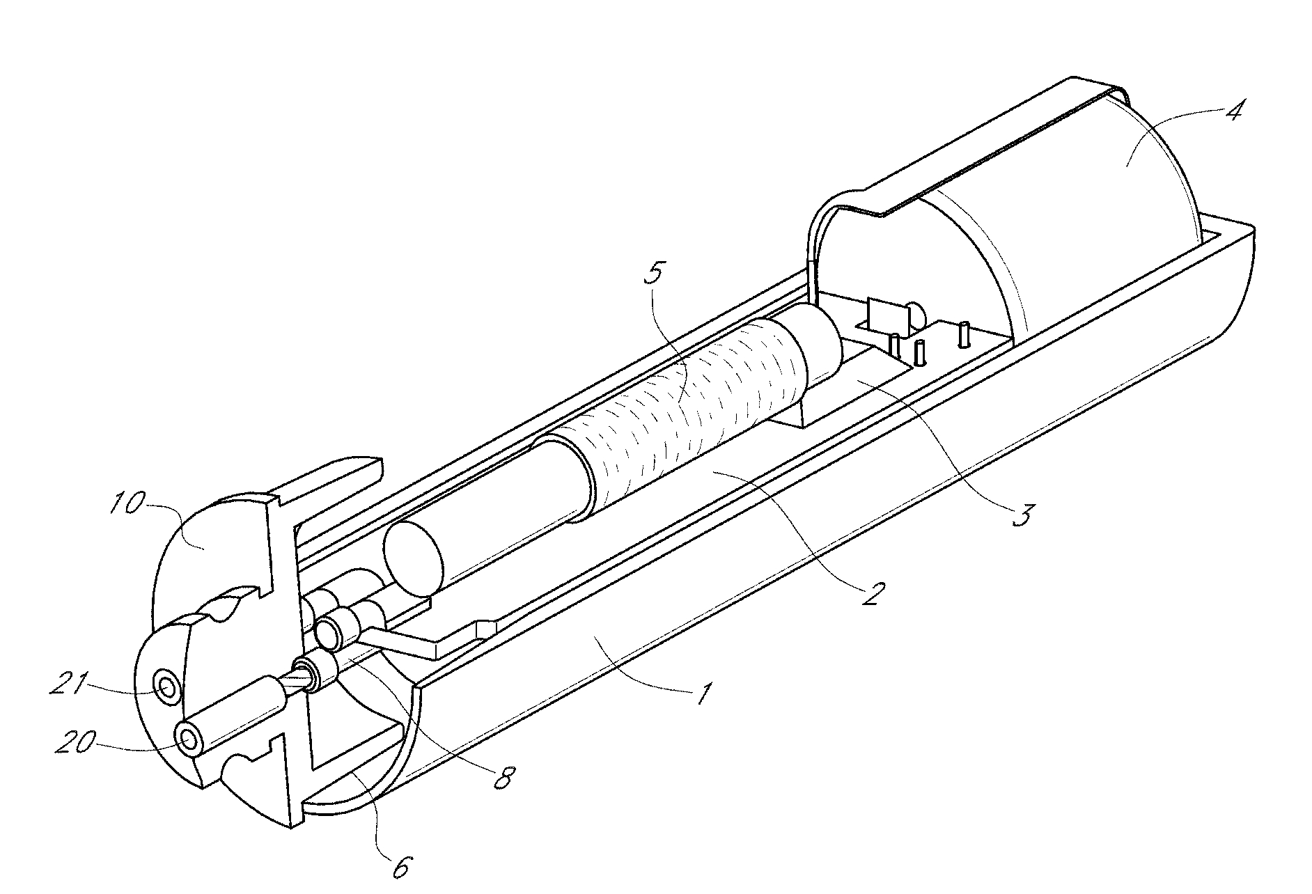
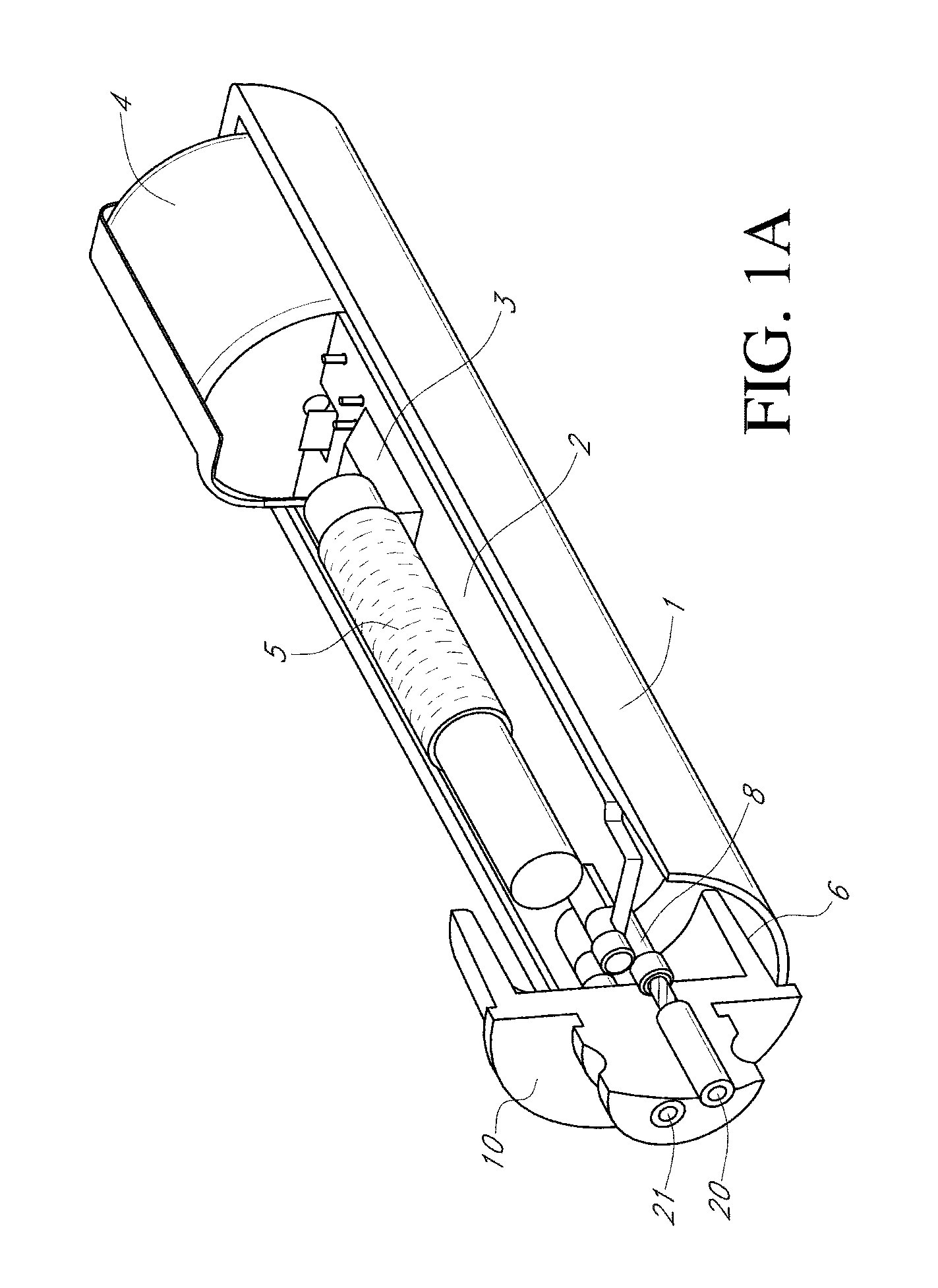
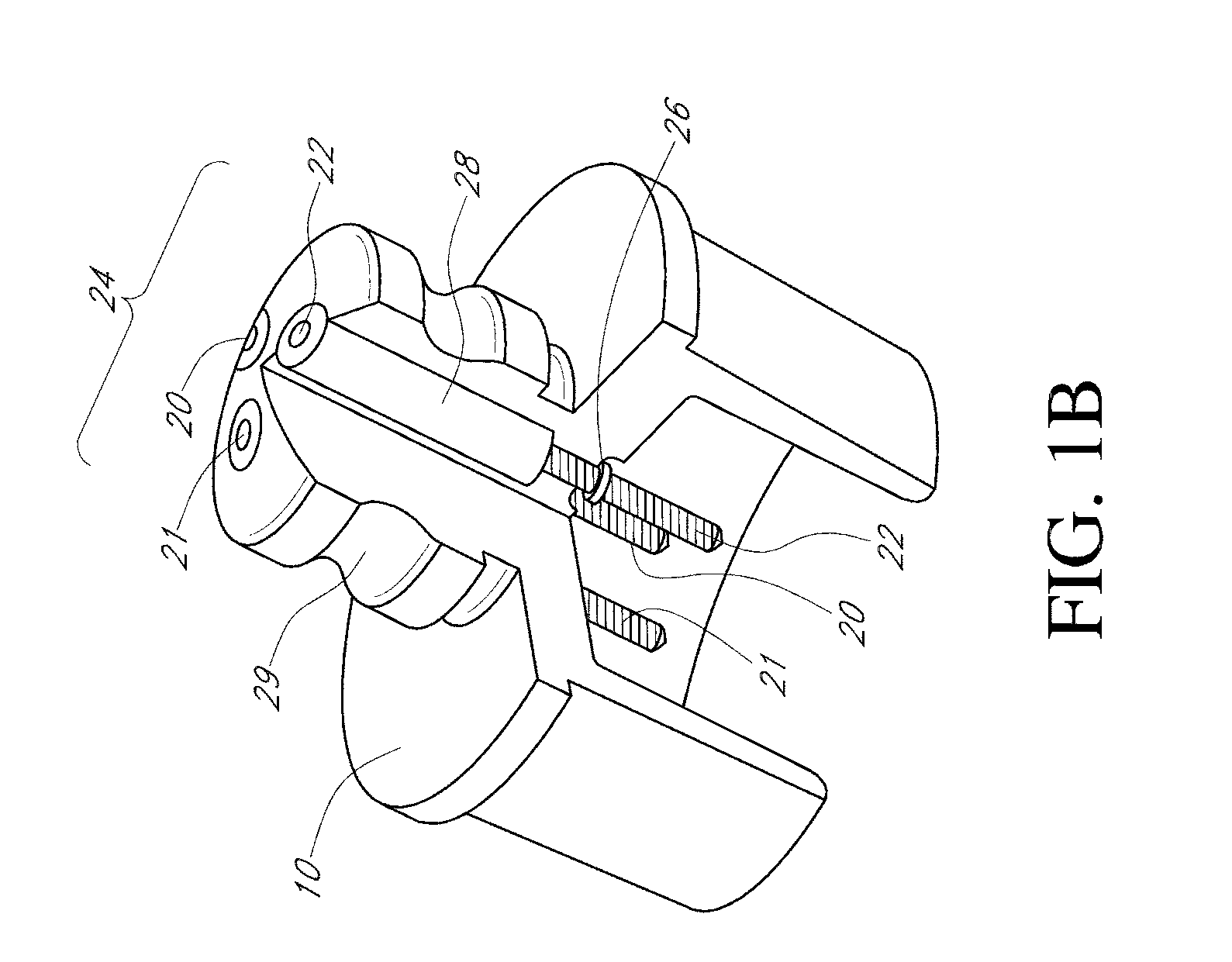
Devices and methods for determining analyte levels are described. The devices and methods allow for the implantation of analyte-monitoring devices, such as glucose monitoring devices that result in the delivery of a dependable flow of blood to deliver sample to the implanted device. The devices include unique architectural arrangement in the sensor region that allows accurate data to be obtained over long periods of time.

Description

CROSS-REFERENCE TO RELATED APPLICATIONS[0001]This application is a continuation of Ser. No. 12 / 696,003, filed Jan. 28, 2010, which is a continuation of Ser. No. 11 / 546,157, filed Oct. 10, 2006, which is a continuation of Ser. No. 11 / 039,269, filed Jan. 19, 2005, now U.S. Pat. No. 7,136,689, which is a continuation of Ser. No. 09 / 916,858, filed Jul. 27, 2001, now U.S. Pat. No. 6,862,465, which is a continuation-in-part of Ser. No. 09 / 447,227, filed Nov. 22, 1999, which is a divisional of Ser. No. 08 / 811,473, filed Mar. 4, 1997, now U.S. Pat. No. 6,001,067.FIELD OF THE INVENTION[0002]The present invention relates generally to devices and methods for determining analyte levels, and, more particularly, to implantable devices and methods for monitoring glucose levels in a biological fluid.BACKGROUND OF THE INVENTION[0003]The continuous measurement of substances in biological fluids is of interest in the control and study of metabolic disorders. Electrode systems have been developed for t...

Claims


Application Information

Patent Timeline
IPC IPC(8): A61B5/05A61B5/00C12Q1/00
CPCA61B5/0031A61B5/14532C12Q1/006A61B5/14865A61B5/14558A61B5/1455A61B5/1459A61B5/1486A61B2562/17
Inventor SHULTS, MARK C.UPDIKE, STUART J.RHODES, RATHBUN K.GILLIGAN, BARBARA J.TAPSAK, MARK A.
Owner DEXCOM
Learn More