Gripper device having holding points

Inactive Publication Date: 2014-12-25
KOREA PNEUMATIC SYST CO LTD
View PDF4 Cites 7 Cited by
  • Summary
  • Abstract
  • Description
  • Claims
  • Application Information

AI Technical Summary

Benefits of technology

[0019]A gripper device according to the present invention has a plurality of holding points and holding units which are disposed at the respective holding points. The holding units that are provided on rotating shafts can be rotated along with the rotating shafts by 90° or 180°. Therefore, whether each holding unit is used to grip a specific object can be optionally determined. Thus, the gripper device according to the present invention can effectively cope with holding points which are changed depending on the kinds of objects, whereby various the gripper device can reliably grip various shapes and sizes of objects.
[0020]The above-mentioned effect

Problems solved by technology

Therefore, if the gripper device has holding points that are set only to a single form, it cannot appropriately cope with various kinds of objects.
However, in this case, preparing different kinds of gripper devices increases a financial burden.
Replacing one gripper device with another kind of gripper device causes time loss, thus reducing productivity.
D

Method used


Image

  • Gripper device having holding points
  • Gripper device having holding points
  • Gripper device having holding points

Examples


Example

DESCRIPTION OF THE REFERENCE NUMERALS IN THE DRAWINGS

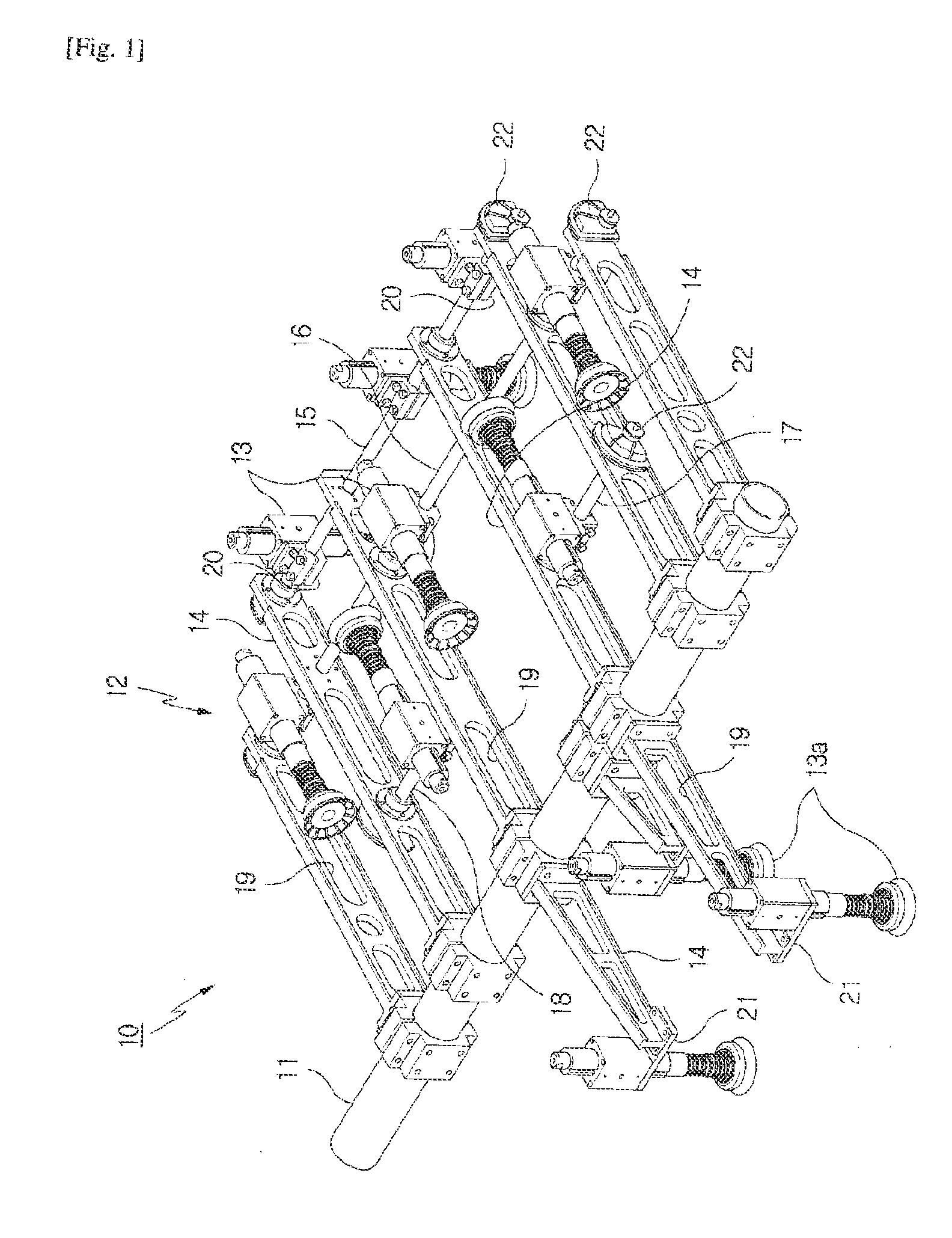
[0025]10. gripper device

[0026]11. pole 12. frame

[0027]13,13a. holding unit 14. support bar

[0028]15,16,17,18. rotating shaft

[0029]20,21. bracket 22. drive unit

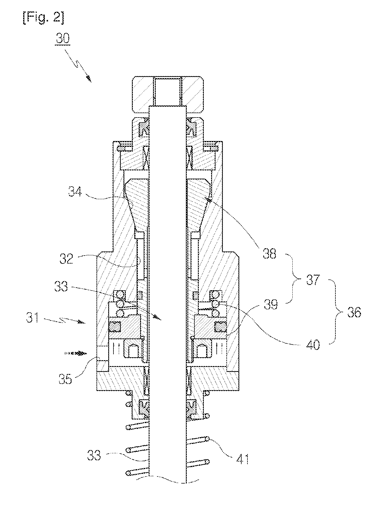
[0030]30. holding unit main body 31. housing

[0031]32. through-hole 33. pipe

[0032]34. inclined surface 35. inlet

[0033]36. locking means 37. chuck

[0034]38. 39. push part

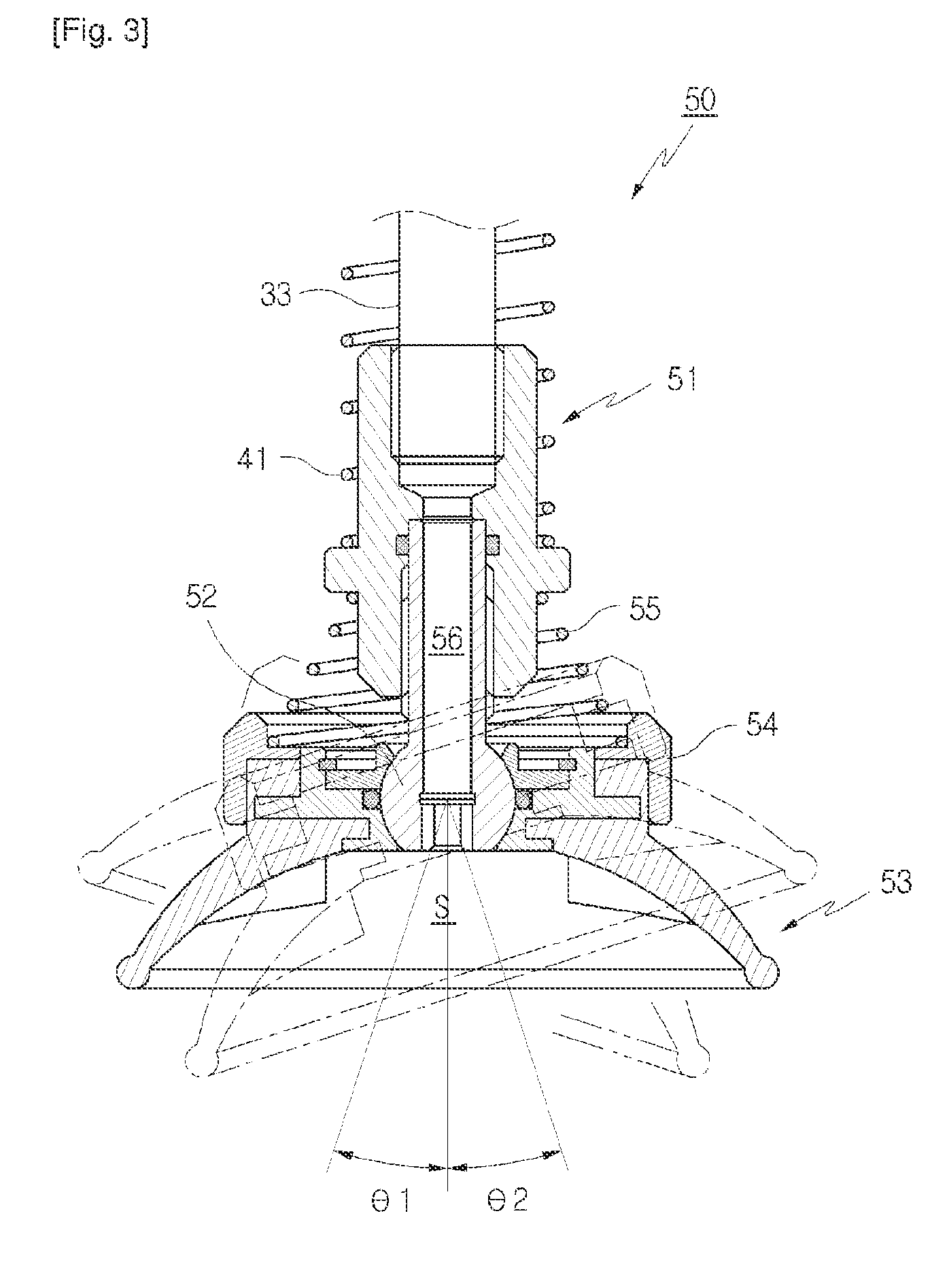
[0035]40. elastic member 41. spring

[0036]50. vacuum gripper 51. body

[0037]52. ball-joint 53. vacuum cup

[0038]34. ring 55. elastic member

[0039]56. passage

[0040]S. inner space

BEST MODE

[0041]The above and other objects, features and advantages of the present invention will be more clearly understood from the following detailed description taken in conjunction with the accompanying drawings. FIG. 1 is a perspective view illustrating the construction of a gripper device according to an embodiment of the present invention. FIG. 2 is a sectional view showing a holding unit used in FIG. 1.

[0042]Referring to FIG. 1, a gr...


PUM


Abstract

The present invention relates to a gripper device which has multiple holding points. The gripper device according to the present invention comprises: a frame comprising a rotating shaft which is arranged in parallel; a holding means fixed by a bracket to one holding point on the rotating shaft; and a driving means which rotates the rotating shaft and the holding means. The gripper device effectively responds to holding points which vary depending on the type of article held so that the articles can be stably held.

Description

TECHNICAL FIELD[0001]The present invention relates, in general, to gripper devices for lifting and transferring objects and, more particularly, to a gripper device having a holding point which is provided with a rotatable holding unit.BACKGROUND ART[0002]Generally, in industrial sites, materials are frequently processed in such a way that they are transferred in stages. For instance, in a site for producing vehicles, a bonnet or an upper plate of a vehicle body is produced through several pressing processes. This sort of object is relatively heavy and has a comparatively large surface area. Therefore, a gripper device having a plurality of holding points is used to reliably grip an object in transferring it between stages. The gripper device is connected to a robotic apparatus so that the object can be lifted and transferred.[0003]In conventional vacuum transfer systems, a vacuum pad is used as a holding unit provided on each holding point. For example, devices introduced in Korean ...

Claims


Application Information

Patent Timeline
IPC IPC(8): B25J15/06B25J15/00
CPCB25J15/0616B25J15/0052Y10S901/40Y10S901/31B25J15/0608B25J15/0061B65G47/91B65G47/918B25J15/06B62D65/18
Inventor CHO, HO-YOUNG
Owner KOREA PNEUMATIC SYST CO LTD
Why Eureka
Try Eureka