Optical computer pointer and optical cursor/frame control method

a computer and frame control technology, applied in the field of computer points, can solve the problems of difficult to precisely control the rotation of a single finger-like ball element, the inherent requirements of the conventional optical mouse, and the limited application of the optical mous

Active Publication Date: 2005-03-24
INTELLECTUAL VENTURES I LLC
View PDF9 Cites 16 Cited by
  • Summary
  • Abstract
  • Description
  • Claims
  • Application Information

AI Technical Summary

Benefits of technology

[0024] In an embodiment, the method further comprises a step of keeping on pushing the triggering button when the plate is fixed at the second position and the margin pattern is detected, thereby further effecting the cursor or frame shift on the display exceeding the level.

Problems solved by technology

The conventional optical mouse, unfortunately, has inherent requirements.
In other words, the application of the optical mouse is restricted.
The rotation of a ball element with a single finger, however, is hard to be precisely controlled.

Method used


Image

  • Optical computer pointer and optical cursor/frame control method
  • Optical computer pointer and optical cursor/frame control method
  • Optical computer pointer and optical cursor/frame control method

Examples


Embodiment Construction

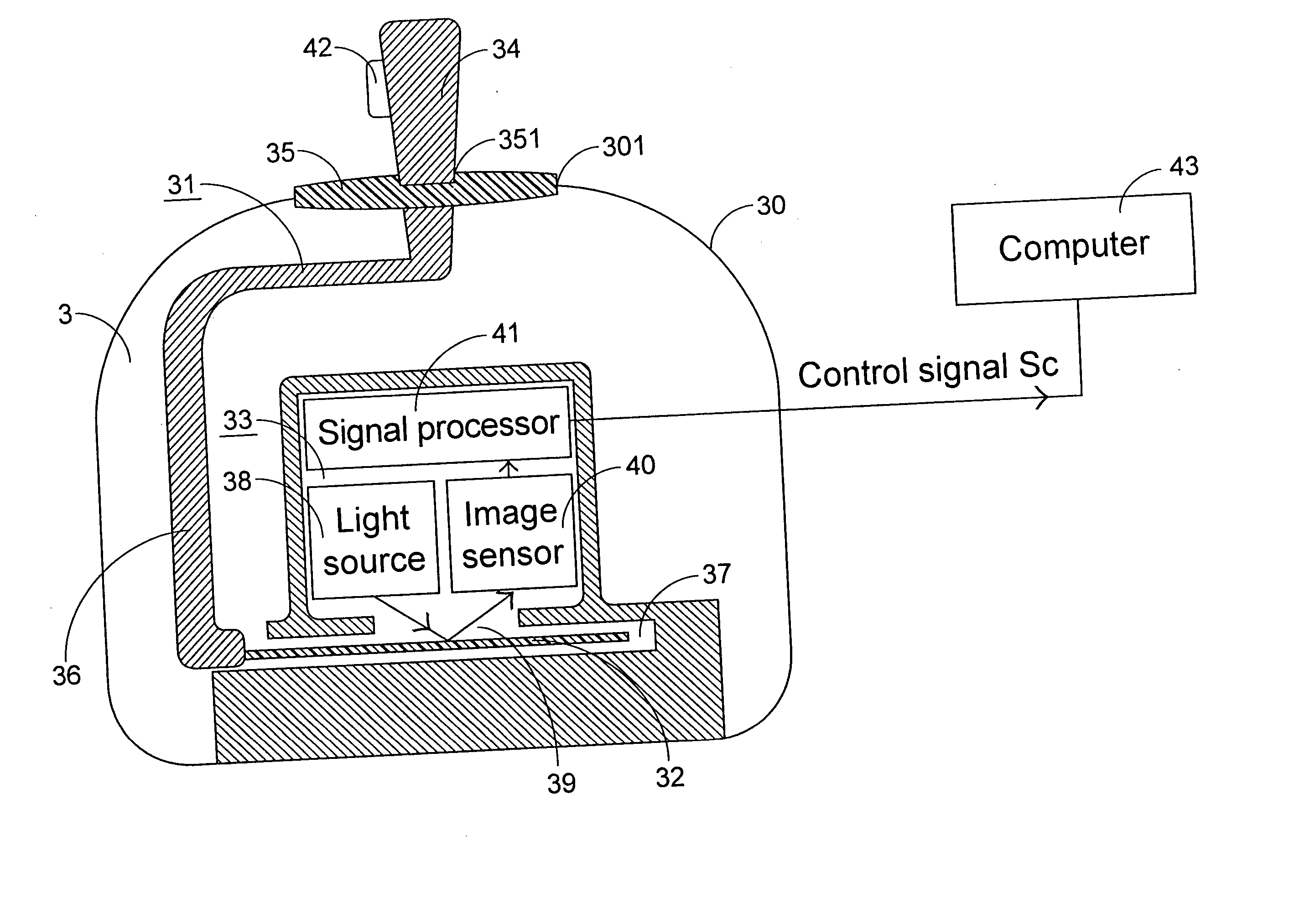
[0034] Referring to FIG. 3, an optical pointer for use with a window interface of a computer to control cursor / frame shift is illustrated. The optical pointer principally comprises a manipulable member 31, a movable plate 32 and a displacement detecting unit 33. The housing 3 of the optical pointer comprises a rigid portion 30 and an elastic portion 35. The rigid portion 30 accommodates therein a portion of the manipulable member 31, the movable plate 32 and the displacement detecting unit 33. The rigid portion 30 has an opening 301 on the top surface thereof. The elastic portion 35 covers the opening 301 of the rigid portion 30 and has an opening 351 in the midst thereof for exposing another portion of the manipulable member 31.

[0035] The movable plate 32 is disposed in a cave structure 37 in the housing 3 and transmitted to effect two-dimensional movement inside the cave 37 by the manipulable member 31. The movable plate 32 has a recognizable pattern for displacement detection, w...


PUM


Abstract

An optical pointer includes a housing, a movable plate, a manipulable member and a displacement detecting unit. The movable plate is disposed in the housing and has a recognizable pattern. The manipulable member is manipulated by a user to transmit the movable plate to effect two-dimensional movement inside the housing. The displacement detecting unit is disposed in the housing for optically detecting the recognizable pattern of the moveable plate, and generating a control signal indicative of a displacement of the movable plate according to detected image change of the recognizable pattern.

Description

FIELD OF THE INVENTION [0001] The present invention relates to a computer pointer, and more particularly to an optical computer pointer for cursor or frame control via a window interface. The present invention also relates to an optical cursor / frame control method, and more particularly to an optical cursor / frame control method for use in a computer with a window interface. BACKGROUND OF THE INVENTION [0002] Optical technologies have been widely employed in pointer systems for cursor or frame control on computer displays. For example, optical mice and optical trackballs are the most popular pointer devices currently. The optical pointer device works by detecting a specified image, tracking the displacement of the specified image, and then generating responsive signals to the computer to conduct the movement of a cursor on the display. [0003] Referring to FIG. 1, a working principle of a conventional optical mouse is schematically shown. The optical mouse principally comprises a hous...

Claims


Application Information

Patent Timeline
Patent Type & Authority Applications(United States)
IPC IPC(8): G01B11/02G05G9/047G06F3/03G06F3/033G06F3/042G09G5/08
CPCG05G9/04788G05G2009/04729G06F3/0338G05G2009/04774G06F3/0317G05G2009/04759
Inventor HSU, WEN-HAOCHEN, HSAING-NANCHIN, HOU-CHING
Owner INTELLECTUAL VENTURES I LLC
Why Eureka
Try Eureka