
Composite gear part for a gear arrangement and a method of forming a composite gear part

a gear arrangement and composite technology, applied in wind energy generation, toothed gearings, liquid fuel engine components, etc., can solve the problems of large cost contribution, high cost, and high cost of wear resistant materials

Inactive Publication Date: 2011-10-13
VESTAS WIND SYST AS
View PDF30 Cites 24 Cited by
  • Summary
  • Abstract
  • Description
  • Claims
  • Application Information

AI Technical Summary

Benefits of technology

[0011]The outer part has a plurality of gear teeth formed therein. Thus, the gear teeth of the gear part are formed completely in the outer part which is fixed circumferentially to the inner part. Accordingly, the inner part does not have gear teeth formed therein, contrary to the composite gear disclosed in US 2007 / 0221005 A1. It is an advantage that the gear teeth are formed entirely in the outer part, because it is thereby obtained that any tooth contact is made by a part which is made entirely from the second material, and very strong teeth can therefore be obtained. Furthermore, this allows the gear teeth to be made in an easier and more precise manner, and it is easier to control a possible post-treatment, e.g. heat treatment, of the gear teeth, because the gear teeth are made from a single material. This is due to the fact that the entire tooth responds in a uniform manner to the post-treatment, and any problems regarding misalignment or distortion due to non-uniform response to a post-treatment are therefore avoided.
[0051]Alternatively or additionally, the step of attaching the outer part onto the inner part may comprise the step of applying an adhesive or a glue to the inner part and / or to the outer part. Thereby it can be even further ensured that the outer part and the inner part are attached firmly to each other. Furthermore, it may not be required to heat the outer part prior to arranging it circumferentially to the inner part. Thereby the risk of elastic distortions in the outer part, including the gear teeth, is considerably reduced.

Problems solved by technology

This is a disadvantage because the wear resistant material is very often expensive and possibly scarce.
Even those expensive and possibly scarce materials as typically used in the industry will typically require an additional thermal treatment or hardening to achieve the desired strength, durability and wear resistance.
Having to heat the entire gear wheel, especially for large gears as used in wind turbines, can be a significant contribution to cost, and consumes considerable amounts of energy.
The material of the inner part may be a low cost material, and the material of the outer part, which normally has the gear teeth formed therein, may be a more expensive and / or scarce material, fulfilling specific requirements, e.g. regarding durability, hardness, wear resistance, etc.

Method used


Image

  • Composite gear part for a gear arrangement and a method of forming a composite gear part
  • Composite gear part for a gear arrangement and a method of forming a composite gear part
  • Composite gear part for a gear arrangement and a method of forming a composite gear part

Examples


first embodiment

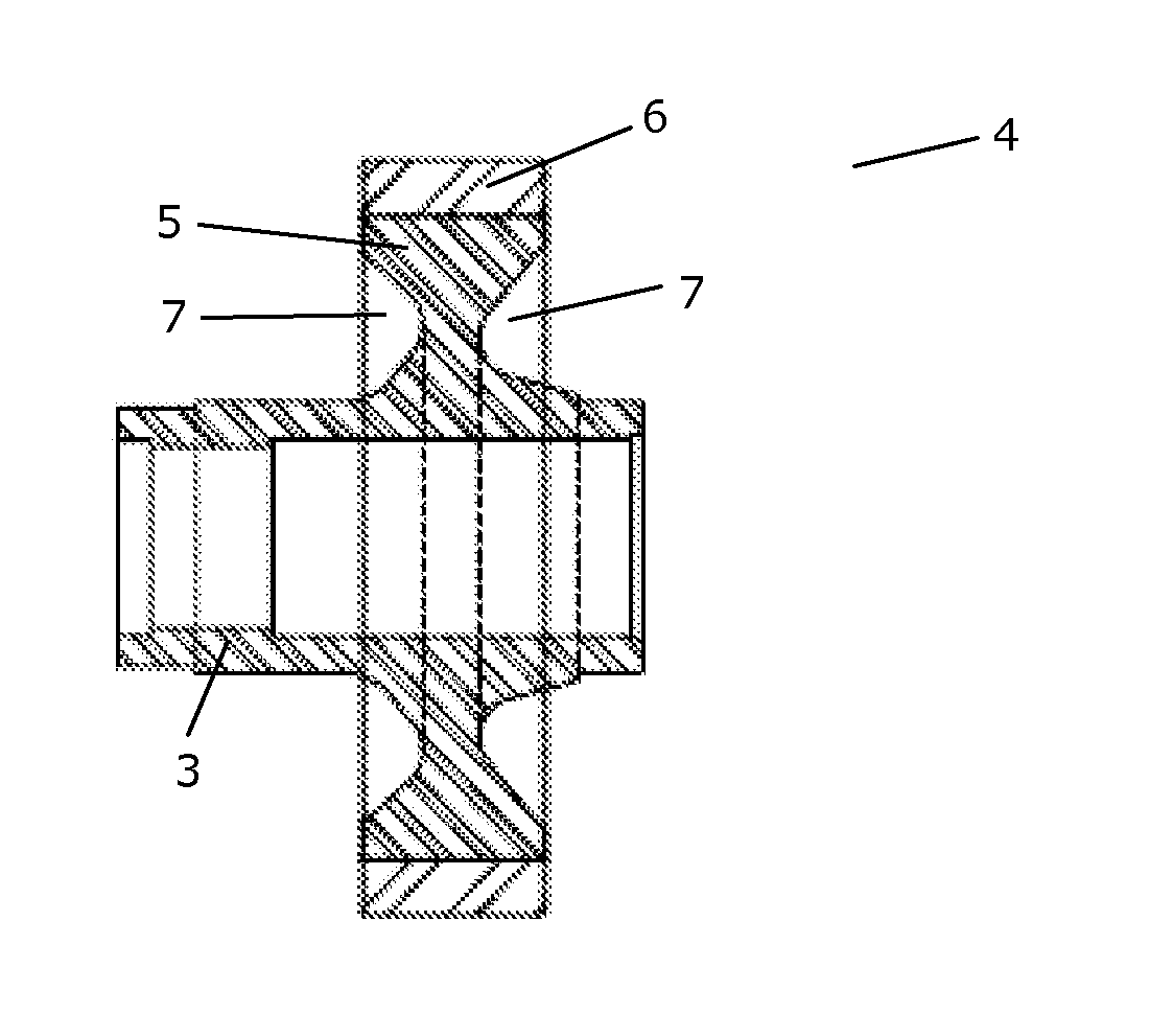
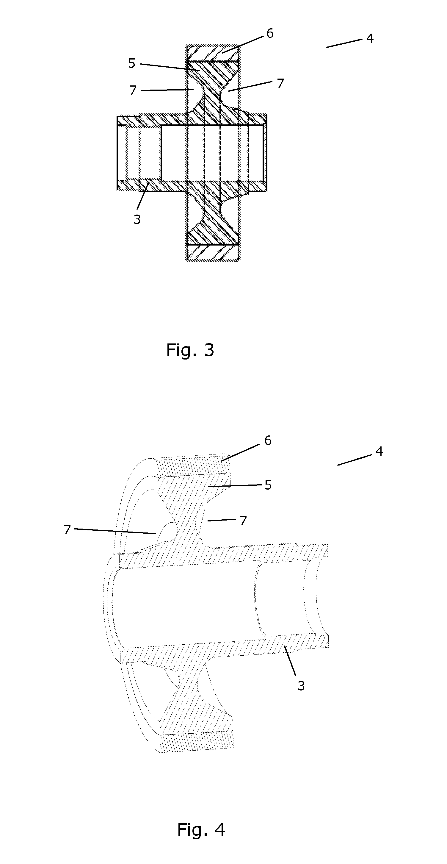
[0059]FIG. 3 is a cross sectional view of a composite gear part according to the invention,

[0060]FIG. 4 is a perspective cross sectional view of the composite gear part of FIG. 3,

second embodiment

[0061]FIG. 5 is a cross sectional view of a composite gear part according to the invention,

[0062]FIG. 6 is a perspective cross sectional view of the composite gear part of FIG. 5,

third embodiment

[0063]FIG. 7 is a cross sectional view of a composite gear part according to the invention,

[0064]FIG. 8 is a perspective cross sectional view of the composite gear part of FIG. 7,


PUM

PropertyMeasurementUnit
Temperatureaaaaaaaaaa
Stiffnessaaaaaaaaaa
Durabilityaaaaaaaaaa

Abstract

A composite gear part (4) for a gear arrangement is disclosed. The composite gear part (4) comprises a shaft part (3) adapted to be rotationally mounted in a gear arrangement, an inner part (5) made from a first material, and an outer part (6) made from a second material, said outer part (6) being fixed circumferentially to the inner part (5), and said outer part (6) having a plurality of gear teeth formed therein. The outer part (6) must be made from a material which is sufficiently durable and hard to fulfil requirements to gear teeth. The material may be a surface hardened high-alloyed steel or a high-alloyed cast iron. The material of the inner part (5) need not fulfil such requirements and may, e.g., be cast iron. Accordingly, the required amount of the more expensive and possibly scarce material is reduced. The inner part (5) is formed integrally with the shaft part (3). Thereby it is not necessary to provide an accurate fit between the inner part (5) and the shaft part (3), and the manufacturing process is made easier and more cost effective. Less material is required in order to obtain sufficient stiffness of the inner part (5) / shaft part (3). The composite gear part (4) is suitable for use in a gear arrangement of a wind turbine.

Description

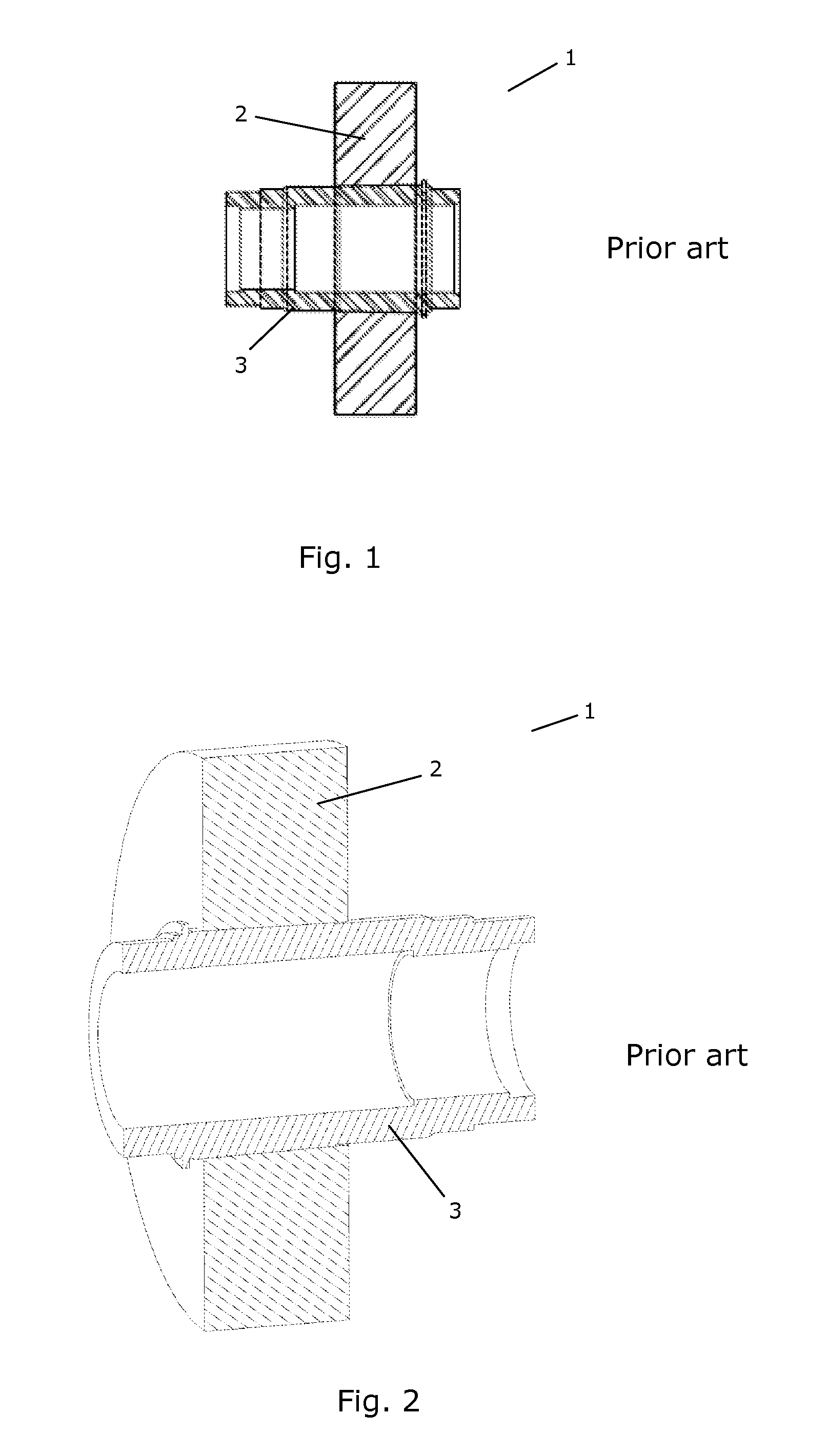
FIELD OF THE INVENTION[0001]The present invention relates to a composite gear part, i.e. a gear part which is formed from two or more materials. More particularly, the present invention relates to a gear part, such as a gear wheel, which is suitable for use in a gear arrangement for a wind turbine. Furthermore, the present invention relates to a method of forming such a composite gear part.BACKGROUND OF THE INVENTION[0002]When manufacturing gears, in particular for large gear arrangements, such as gear arrangements which are suitable for use in drive trains for wind turbines, it is often necessary to manufacture, at least the teeth of the gear wheels, from a wear resistant material in order to prevent damage to the gear wheels, misalignment and uneven loads on the gear teeth during use. Normally, the entire gear wheel is manufactured from the wear resistant material. This is a disadvantage because the wear resistant material is very often expensive and possibly scarce. Accordingly, ...

Claims


Application Information

Patent Timeline
IPC IPC(8): F16H1/02B23P15/14B32B37/12F03D11/02
CPCB23P11/025F03D11/02F05B2260/4031F05B2280/5007F05C2251/10Y10T74/19F16H55/17F16H2055/065Y02E10/722Y10T29/49465F16H55/06F03D15/00F03D15/10F03D80/70Y02E10/72Y10T29/49462Y10T74/19921Y02P70/50
Inventor DEMTRODER, JENS
Owner VESTAS WIND SYST AS
Learn More