Frame unit for video display devices, and video display device

a video display device and frame unit technology, applied in the field of frame units for video display devices and to video display devices, can solve the problems of troublesome video image viewing, time-consuming and laborious bonding, etc., and achieve the effect of convenient and precise manner

Inactive Publication Date: 2010-12-09
SONY CORP
View PDF10 Cites 4 Cited by
  • Summary
  • Abstract
  • Description
  • Claims
  • Application Information

AI Technical Summary

Benefits of technology

[0014]According to the embodiments of the present invention, the polarizers can be mounted on the video display unit in an easy and precise manner as desired.

Problems solved by technology

Problems with these polarizing plates are that it takes a considerable time and effort to bond and that the surfaces of the polarizing plates bonded to the forefront surfaces of the video display device reflect the outside light and cause trouble viewing video images.

Method used


Image

  • Frame unit for video display devices, and video display device
  • Frame unit for video display devices, and video display device
  • Frame unit for video display devices, and video display device

Examples


Embodiment Construction

[0025]A best mode (referred to below as an embodiment) for carrying out the present invention will now be described in the following order:

[0026]1. Frame units for video display devices (exemplary basic structure of frame unit, exploded perspective view, mounted and unmounted states, exemplary linear structure, exemplary matrix structure)

[0027]2. Video display device (exemplary structure of a frame unit, viewing of video images)

[0028]3. Exemplary structures of light emitting units (rectangular package, round package)<

1. Frame units for video display devices>

[Basic Structure of Frame Unit]

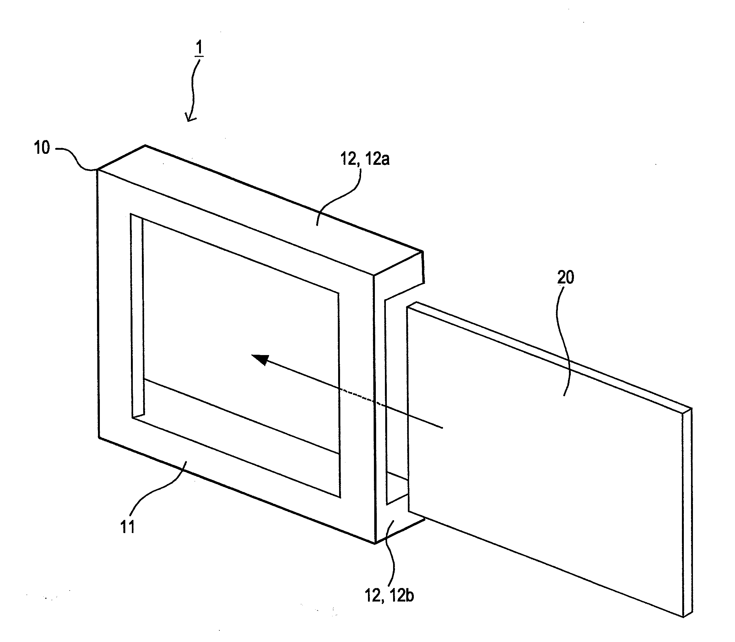
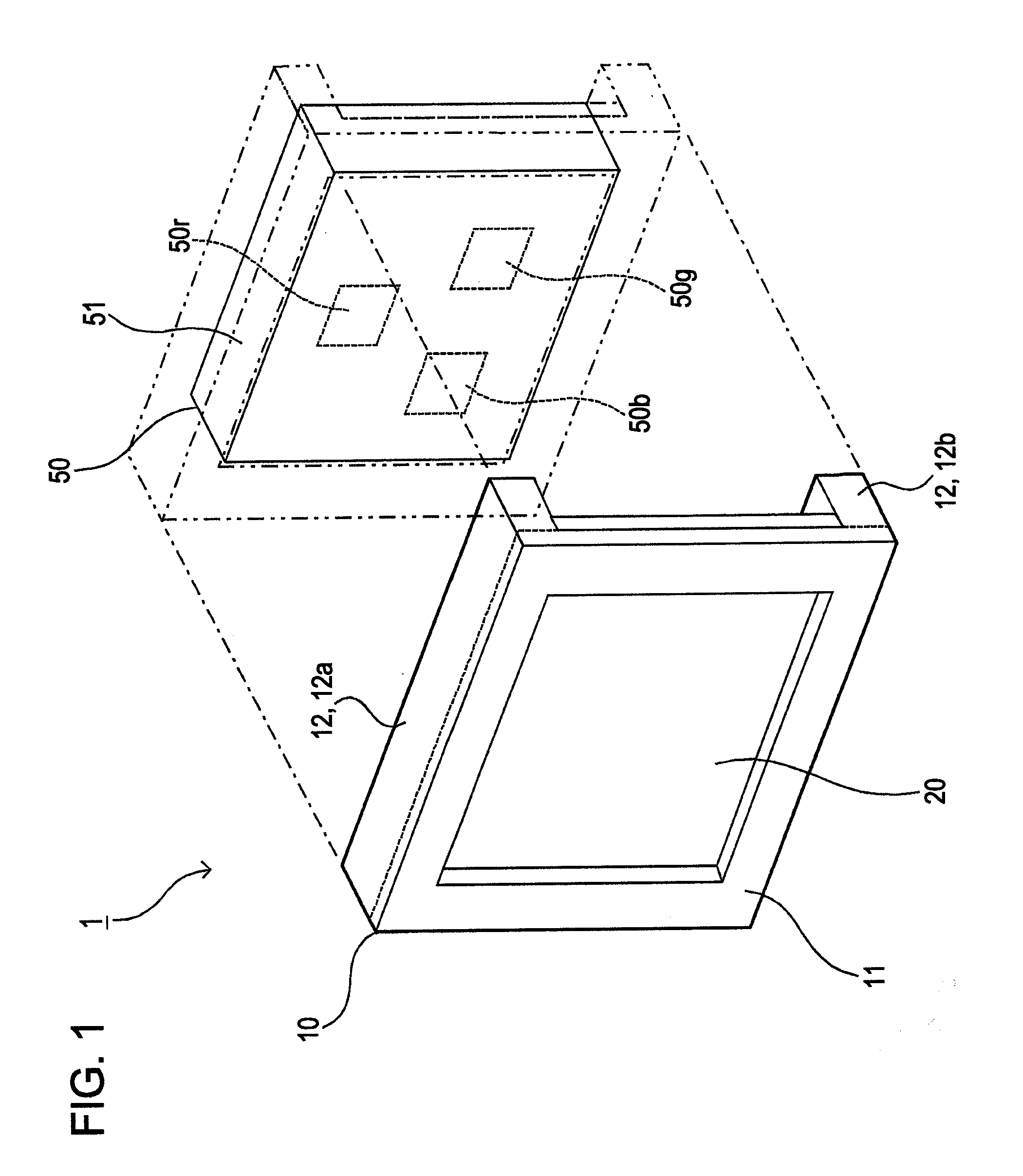
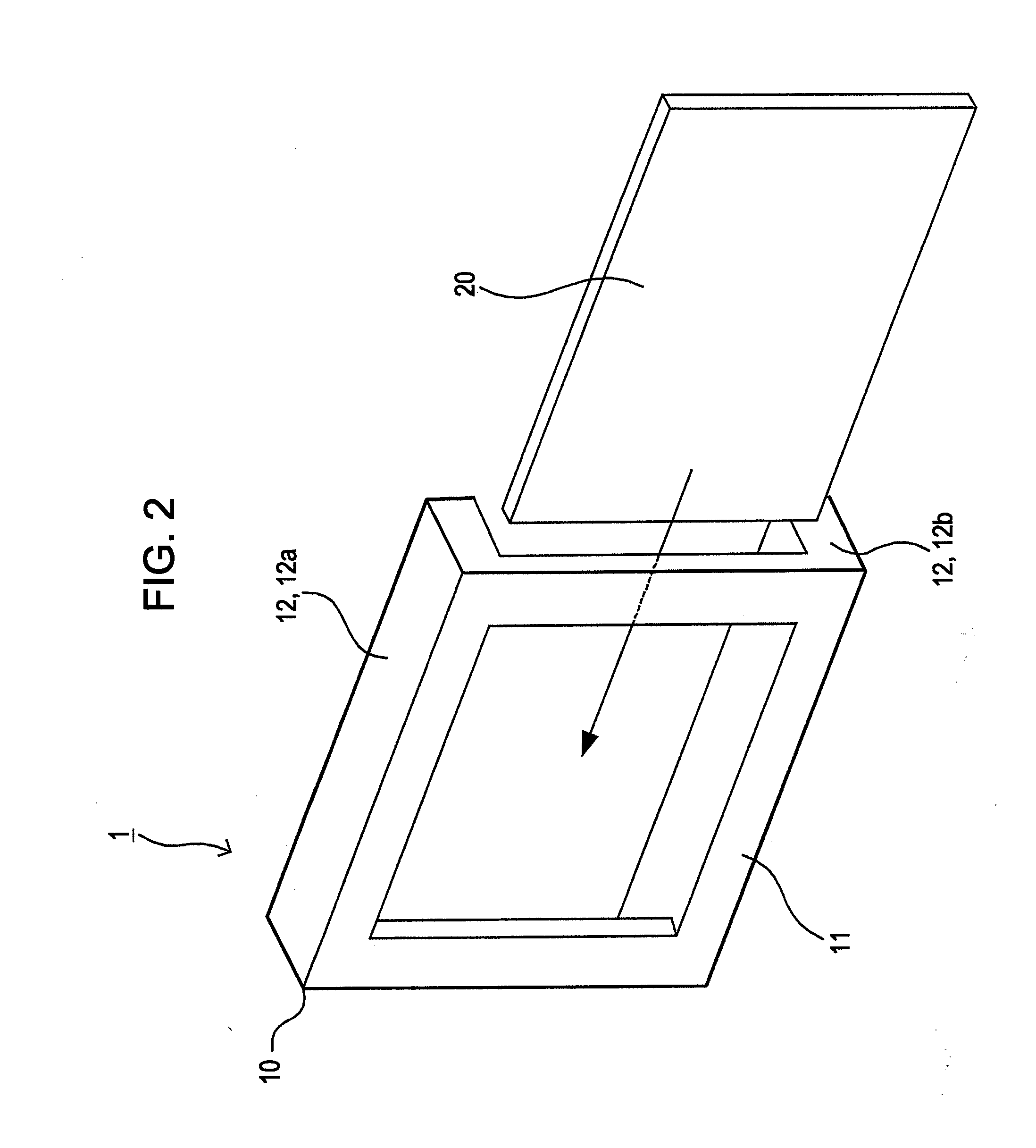
[0029]FIG. 1 is a perspective view illustrating the basic structure of a frame unit according to an embodiment of the present invention. The frame unit 1 with the basic structure accommodates a single light emitting unit 50. The frame unit 1 includes a frame 10 and a polarizer 20.

[0030]The frame 10 has a frame body 11 and mutually facing legs 12. The frame body 11 is a frame-shaped member correspond...


PUM


Abstract

A frame unit for a video display device includes a frame and a polarizer. The frame has a frame body and a plurality of mutually facing legs. The frame body is disposed around a light emitting unit and the legs extend from the frame body and are fitted along side surfaces of the light emitting unit. The polarizer extends between the mutually facing legs of the frame.

Description

CROSS REFERENCE TO RELATED APPLICATIONS[0001]The present application claims priority to Japanese Patent Application JP 2009-134787 filed in the Japan Patent Office on Jun. 4, 2009, the entire content of which is hereby incorporated by reference.BACKGROUND OF THE INVENTION[0002]1. Field of the Invention[0003]The present invention relates to a frame unit for video display devices and to a video display device. More specifically, the present invention relates to a frame unit on which a polarizing plate for a video display device can be mounted if necessary and to a video display device.[0004]2. Description of the Related Art[0005]In recent years, large-sized video display devices employing light emitting diodes (LEDs), plasma display panels (PDP), fluorescent tubes, fluorescent lamps, etc. are in widespread use. In addition, there are devised techniques for emitting light from odd and even lines in vibration directions orthogonal to each other to enable stereoscopic video images to be ...

Claims


Application Information

Patent Timeline
Patent Type & Authority Applications(United States)
IPC IPC(8): H04N5/64G02B30/25
CPCG02B5/3025H04N13/0434G02B27/26G02B7/006G02B30/25H04N13/337H04N5/64H04N13/00
Inventor MURATA, HIDEOOGAWA, SHIGEYUKI
Owner SONY CORP
Why Eureka
Try Eureka