Position determination II - calculation

a position determination and calculation technology, applied in the field of position determination iicalculation, can solve the problems of no explanation as to how the checkered pattern is constructed or how, the risk of incorrect position determination, and the production of the patterned writing surfa

Inactive Publication Date: 2005-05-19
ANOTO IP LIC
View PDF8 Cites 12 Cited by
  • Summary
  • Abstract
  • Description
  • Claims
  • Application Information

AI Technical Summary

Benefits of technology

The technical effect of this patent is that it provides a way for products to have many different codes on them at once. This helps make things easier when trying to track or locate these products.

Problems solved by technology

The technical problem addressed in this patent is the difficulty in creating a precise position detection system for surfaces. Current methods use complex symbols or require sensors to capture multiple signals simultaneously, leading to poor accuracy and high costs. Additionally, current systems struggle to identify small patterns within the context of other objects.

Method used


Image

  • Position determination II - calculation
  • Position determination II - calculation
  • Position determination II - calculation

Examples


Embodiment Construction

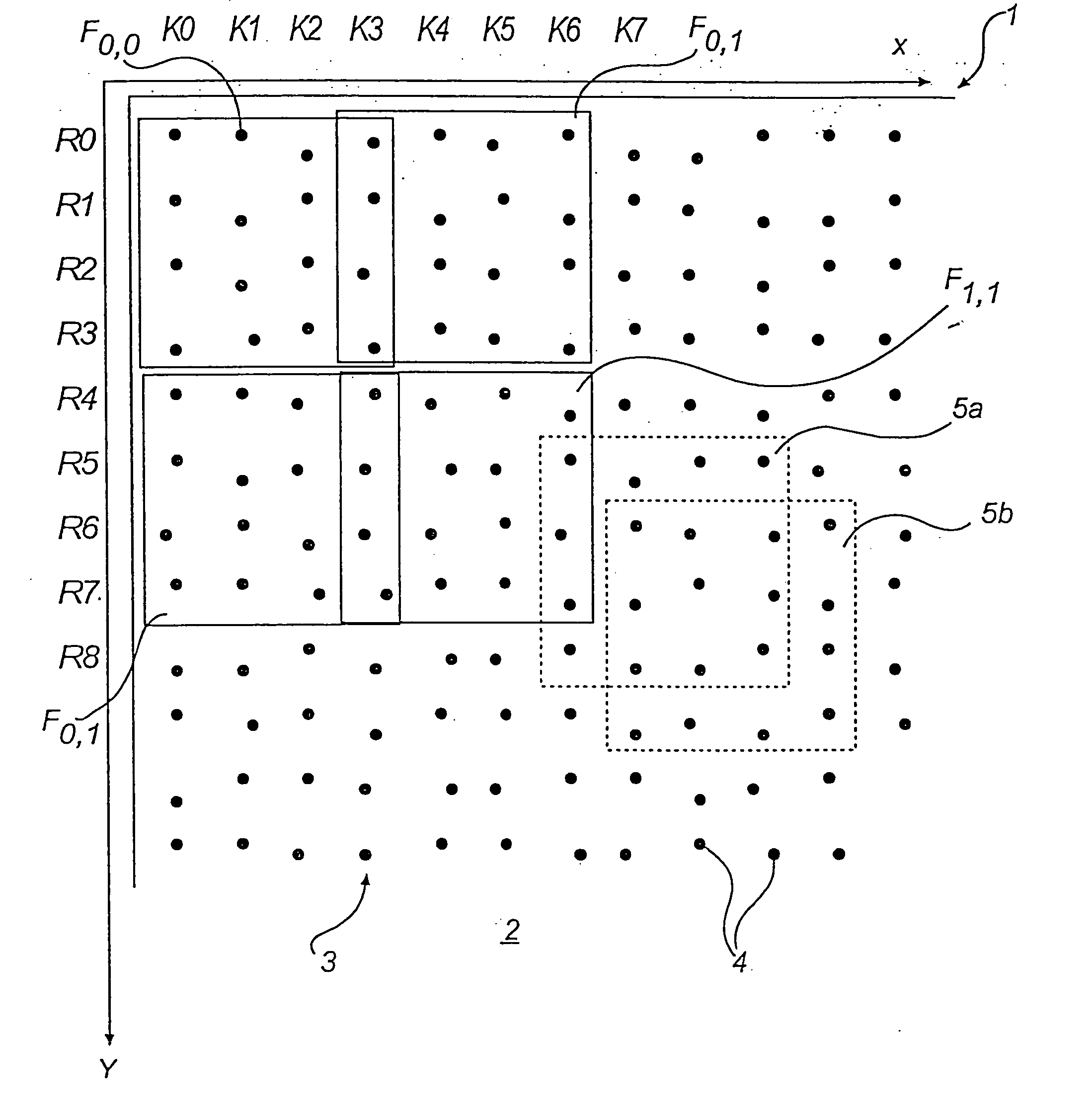
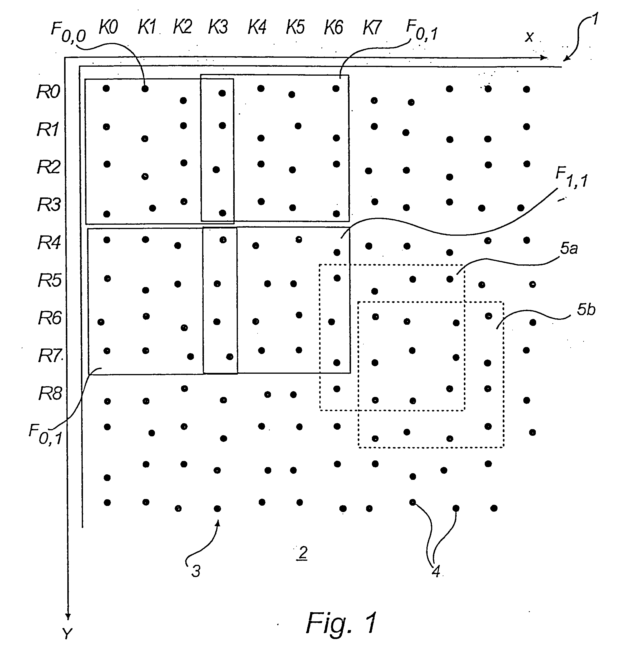
[0066]FIG. 1 shows a part of a product in the form of a sheet of paper 1, which on at least part of its surface 2 is provided with an optically readable position-coding pattern 3 which makes possible position determination.

[0067] The position-coding pattern comprises marks 4, which are systematically arranged across the surface 2, so that it has a “patterned” appearance. The sheet of paper has an X-coordinate axis and a Y-coordinate axis. The position determination can be carried out on the whole surface of the product. In other cases the surface which enables position determination can constitute a small part of the product.

[0068] The pattern can, for example, be used to provide an electronic representation of information which is written or drawn on the surface. The electronic representation can be provided, while writing on the surface with a pen, by continuously determining the position of the pen on the sheet of paper by reading the position-coding pattern.

[0069] The positio...


PUM


Abstract

A method of providing a position code on a surface, which position code codes a plurality of positions on the surface. A cyclic number series is used, which has the characteristic that the position in the number series of each number sequence of a first predetermined length is determined unambiguously. The number series is printed out a plurality of times across the surface, different rotations of the first cyclic number series being used so that displacements arise between adjacent number series. The surface is divided into a plurality of code windows, which comprise at least three number series and have one number series overlapping one number series of adjacent code windows. The position of the code windows in the x-direction is coded by means of the displacements between the cyclic number series belonging to the code window. A second number series is used for coding in the y-direction. The invention also concerns a method and a device for determining the position, and a device and a computer program product for implementing the method.

Description


Claims


Application Information

Patent Timeline
Owner ANOTO IP LIC
Why Eureka
Try Eureka