

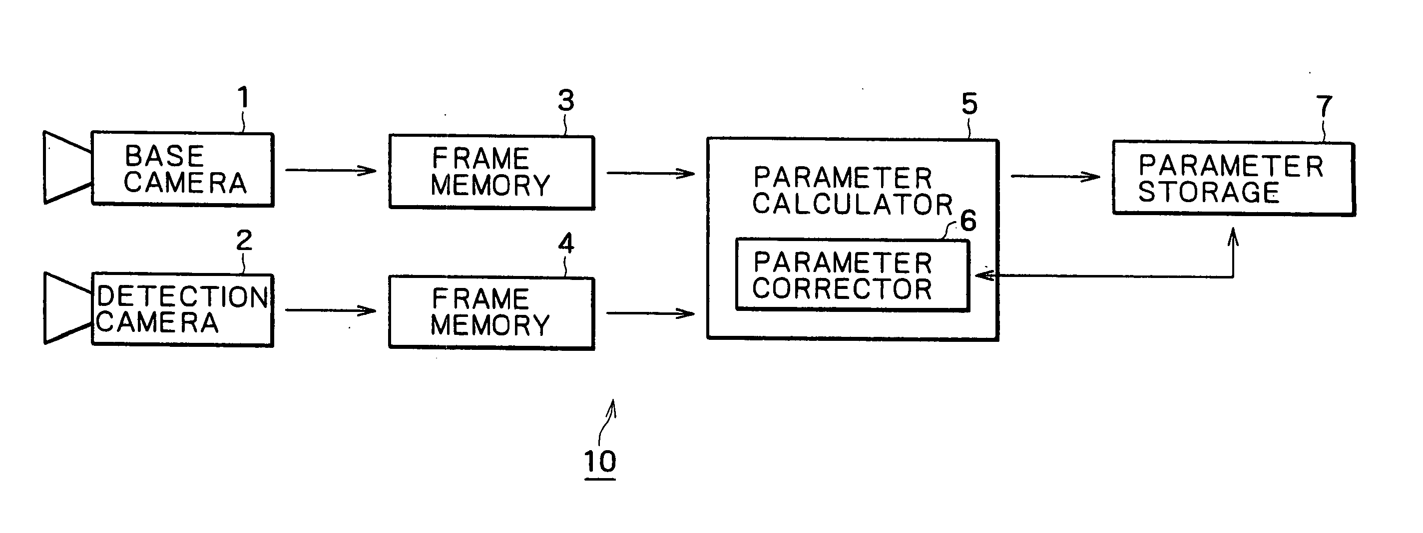
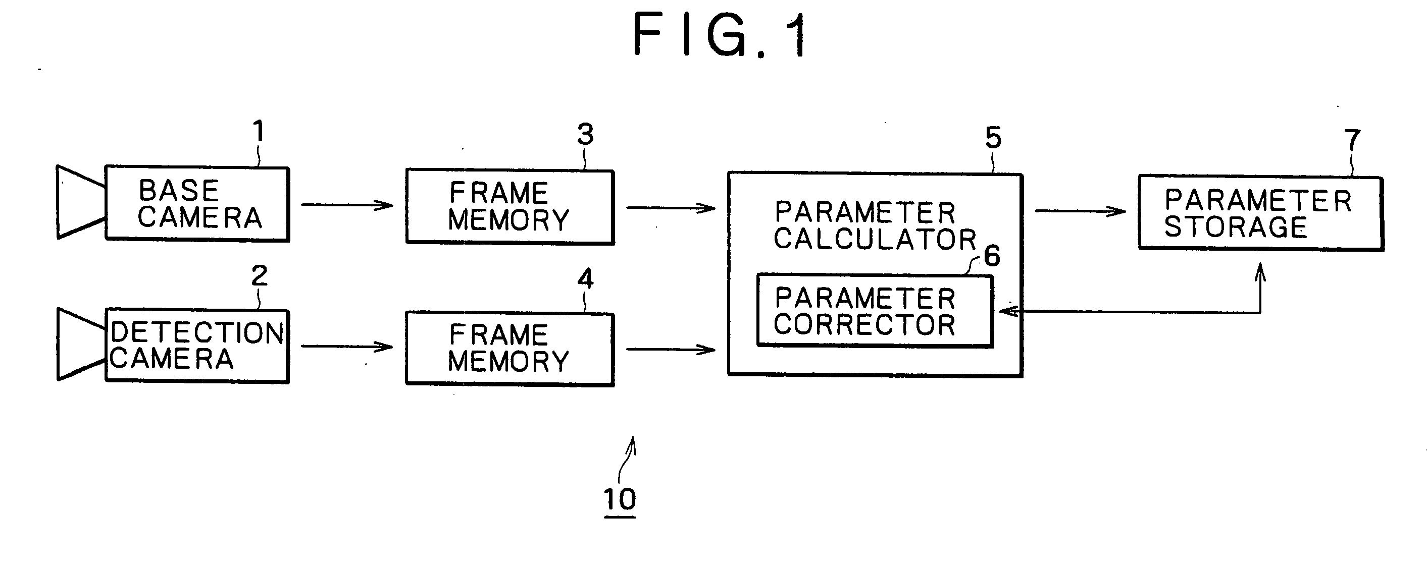
Camera calibration device and method, and computer system
a calibration method and camera technology, applied in the field of camera calibration methods and devices, can solve the problems of no established calibration method, no accurate stereography depth measurement, and inability to obtain an accurate projected image from the front image, etc., and achieve the effect of simplifying calibration
- Summary
- Abstract
- Description
- Claims
- Application Information
AI Technical Summary
Benefits of technology
Problems solved by technology
Method used
Image

Examples
Embodiment Construction
[0050] Prior to describing some preferred embodiments of the present invention, an explanation will be given on camera parameters used in this specification and also on a method of distance measurement carried out on the basis of such parameters.
[0051] In the following description, a point on an image is expressed as
m=[u,v]T
[0052] Similarly, a point in space is expressed as
M=[x,y,z]T
[0053] And the points in homogeneous coordinates are expressed respectively as m~=[u,v,1]TM~=[x,y,z]T
[0054] In this case, the relationship between the space point M and the image point m is represented by an equation given below. sm~=A·[R,t]·M~=P·M~(1)
[0055] In the above equation, s denotes a scale factor, and a matrix [R,t] is termed an external parameter which signifies the position of a camera in space. R and t denote, respectively, a rotation matrix and a translation matrix of the image. And a matrix A is termed an internal parameter of a camera expressed by the following equation. A=[αγu0...
PUM
 Abstract
Description
Claims
Application Information