Control method for multiple heat pump

a control method and heat pump technology, applied in the field of multiple heat pumps, can solve the problems of deterioration of heating performance, damage, short life of compressors, etc., and achieve the effect of minimizing the heating effect of the shutdown of indoor units and rapid recovery of liquid refrigeran

Active Publication Date: 2005-09-08
LG ELECTRONICS INC
View PDF10 Cites 12 Cited by
  • Summary
  • Abstract
  • Description
  • Claims
  • Application Information

AI Technical Summary

Benefits of technology

[0021] Therefore, the present invention has been made in view of the above problems, and it is an object of the present invention to provide a control method for a multiple heat pump which can return a liquid refrigerant, remaining in shutdown indoor units, into compressors when only one of multiple indoor units operates in a heating mode, so as to enhance cooling efficiency of the compressors using the refrigerant, thereby extending life-span of the compressors as well as improving heating performance.
[0042] With such a control method for a multiple heat pump according to the present invention, when one of multiple indoor units operates in a heating mode and the other indoor units shut down, electronic expansion valves of the shutdown indoor units are controlled to have an opening degree higher than a standard opening degree if an outlet temperature of compressors is higher than a preset temperature, so as to permit a liquid refrigerant, remaining in the shutdown indoor units, to be recovered to the compressors. This can solve a conventional refrigerant shortage problem of the compressors, preventing a deterioration of heating performance and a reduction of life-span of the compressors.
[0044] Furthermore, the control method for the multiple heat pump according to the present invention can stepwise increase the opening degree of the electronic expansion valves of the shutdown indoor units, minimizing heating effects of the shutdown indoor units and enabling rapid recovery of the liquid refrigerant.

Problems solved by technology

Such an overheating of the compressors 22 increases an outlet side temperature of the compressors, resulting in a deterioration of heating performance as well as damage and shorter life-span of the compressors 22.

Method used


Image

  • Control method for multiple heat pump
  • Control method for multiple heat pump
  • Control method for multiple heat pump

Examples


first embodiment

[0065]FIG. 6 is a flow chart illustrating a control method for the multiple heat pump according to the present invention.

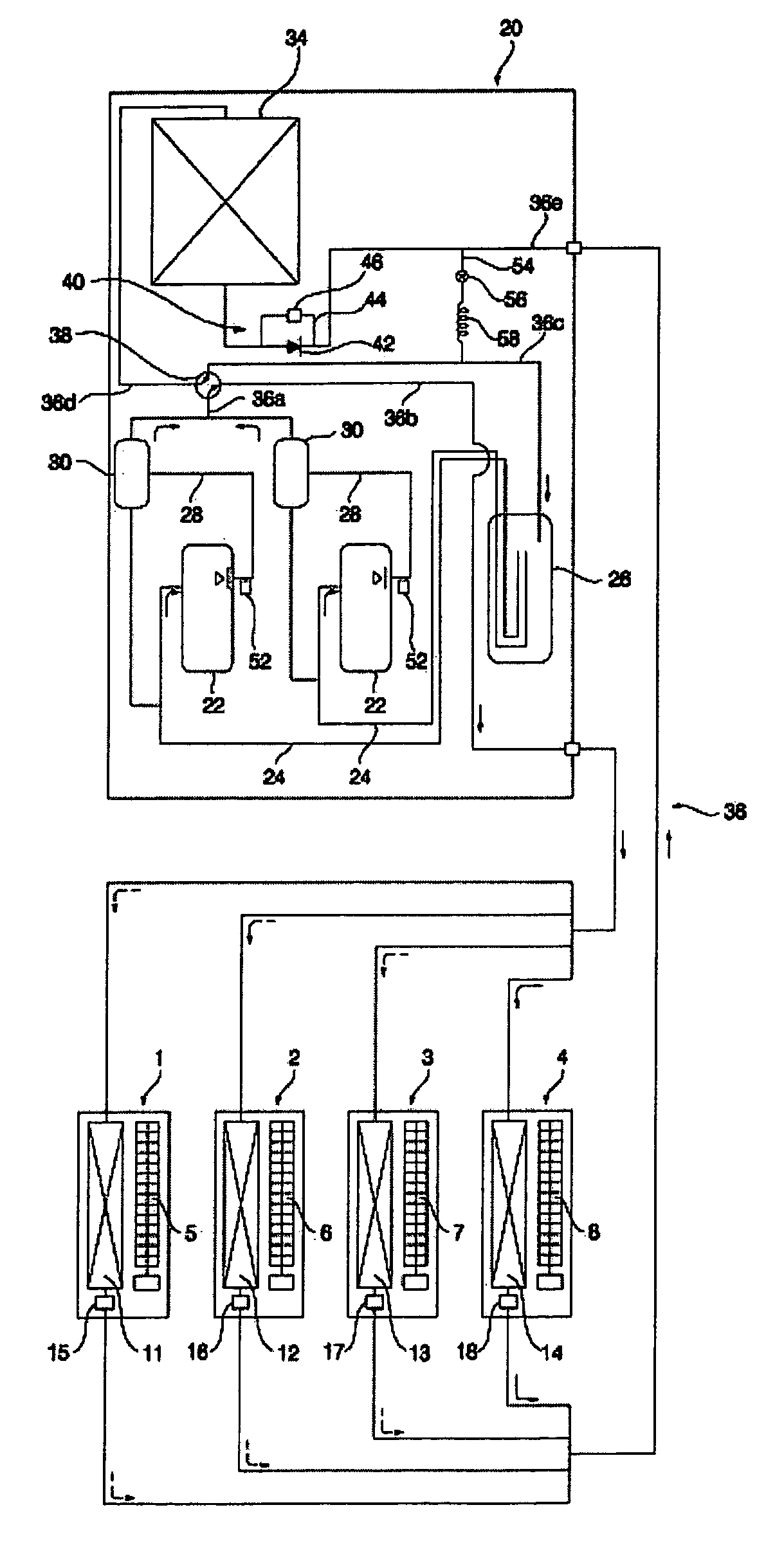
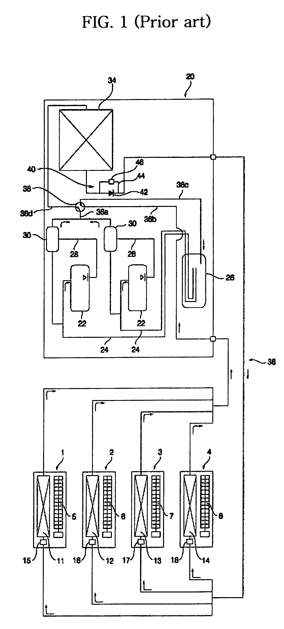
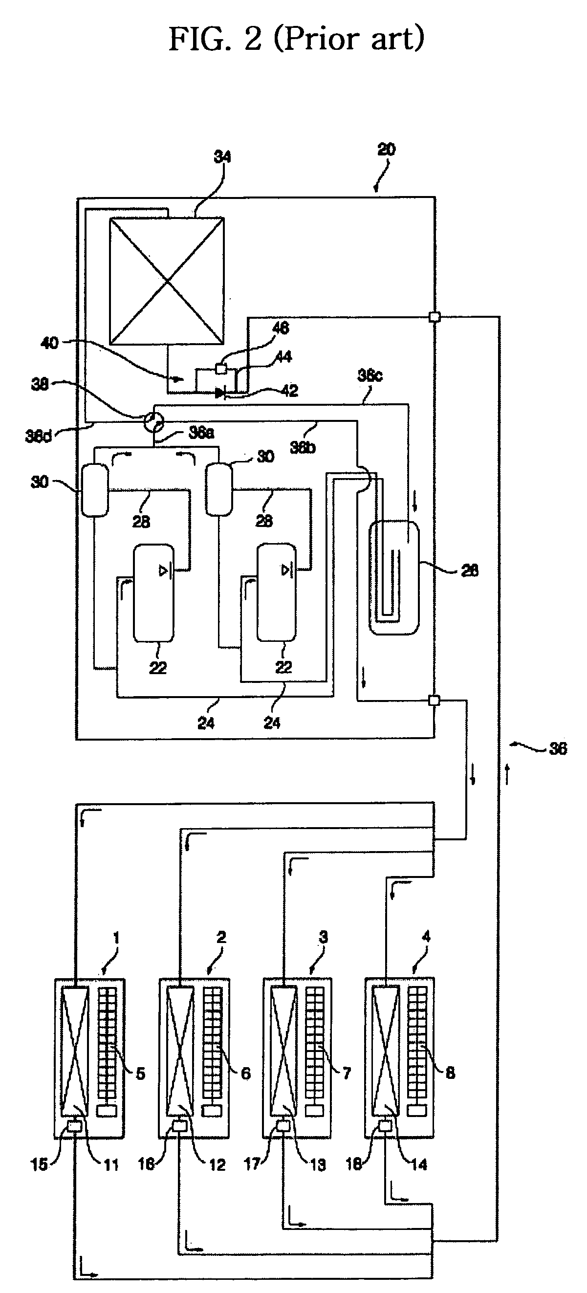
[0066] First, when one of the multiple indoor units 4 operates in a heating mode and the other indoor units 1, 2 and 3 shut down, the control unit 62 compares a temperature T sensed by the outlet temperature sensors 52 with a first preset temperature T1 (S1 and S2).

[0067] Here, the first preset temperature T1 is a standard temperature for determining whether or not an opening degree of the electronic expansion valves 15, 16 and 17 of the shutdown indoor units 1, 2 and 3 has to be changed.

[0068] If the temperature T sensed by the outlet temperature sensors 52 is higher than the first preset temperature T1, the control unit 62 controls the electronic expansion valves 15, 16 and 17 of the shutdown indoor units 1, 2 and 3 to attain an opening degree X1 higher than a standard opening degree X0 (S3).

[0069] The standard opening degree X0 is a standard preset opening d...

second embodiment

[0074]FIG. 7 is a flow chart illustrating a control method for the multiple heat pump according to the present invention.

[0075] First, when one of the multiple indoor units 4 operates in a heating mode and the other indoor units 1, 2 and 3 shut down, the control unit 62 compares a temperature T sensed by the outlet temperature sensors 52 with a first preset temperature T1 (S11 and S12).

[0076] Here, the first preset temperature T1 is a standard temperature for determining whether or not an opening degree of the electronic expansion valves 15, 16 and 17 of the shutdown indoor units 1, 2 and 3 have to be changed and for determining whether or not the bypass valve 56 has to be opened.

[0077] If the temperature T sensed by the outlet temperature sensors 52 is higher than the first preset temperature T1, the control unit 62 opens the bypass valve 56 so as to divert part of the refrigerant and recover it to the compressors 22 after expansion. At the same time, the control unit 62 controls...

third embodiment

[0088]FIG. 8 is a flow chart illustrating a control method for the multiple heat pump according to the present invention.

[0089] First, when one of the multiple indoor units 4 operates in a heating mode and the other indoor units 1, 2 and 3 shut down, the control unit 62 compares a temperature T sensed by the outlet temperature sensors 52 with a first preset temperature T1 (S21 and S22).

[0090] Here, the first preset temperature T1 is a standard temperature for determining whether or not the opening degree of the electronic expansion valves 15, 16 and 17 of the shutdown indoor units 1, 2 and 3 has to be changed to a first opening degree and for determining whether or not the bypass valve 56 has to be opened.

[0091] If the temperature T sensed by the outlet temperature sensors 52 is higher than the first preset temperature T1, the control unit 62 opens the bypass valve 56 so as to divert part of the refrigerant and recover it to the compressors 22 after expansion. At the same time, th...


PUM


Abstract

Disclosed herein is a control method for a multiple heat pump. In the control method, when one of multiple indoor units operates in the heating mode and the other indoor units shut down, electronic expansion valves of the shutdown indoor units are controlled to have an opening degree higher than a standard opening degree if an outlet temperature of compressors is higher than a preset temperature, so as to permit a liquid refrigerant, remaining in the shutdown indoor units, to be more readily recovered to the compressors. This eliminates a refrigerant shortage phenomenon of the compressors and prevents deterioration of heating performance as well as reduction of life-span of the compressors.

Description

BACKGROUND OF THE INVENTION [0001] 1. Field of the Invention [0002] The present invention relates to a multiple heat pump, and more particularly, to a control method for a multiple heat pump which can return a liquid refrigerant, remaining in shutdown indoor units, into compressors when only one of multiple indoor units operates in a heating mode. [0003] 2. Description of the Related Art [0004]FIG. 1 is a schematic cycle diagram illustrating refrigerant flow in a cooling mode of a conventional multiple heat pump. FIG. 2 is a schematic cycle diagram illustrating refrigerant flow in a heating mode of the conventional multiple heat pump. FIG. 3 is a schematic cycle diagram illustrating refrigerant flow when one of multiple indoor units of the conventional multiple heat pump operates in a heating mode and the other indoor units shut down. [0005] As shown in FIGS. 1 to 3, the conventional multiple heat pump comprises multiple indoor units 1, 2, 3 and 4. Each of the indoor units 1, 2, 3 o...

Claims


Application Information

Patent Timeline
Patent Type & Authority Applications(United States)
IPC IPC(8): F25B13/00F25B41/06F25B49/02F24F11/00
CPCF25B13/00F25B2313/02323F25B2313/02741F25B2700/21152F25B2400/19F25B2600/2513F25B2400/075
Inventor HWANG, IL NAHMOH, SAI KEELEE, YOON BEENCHANG, SE DONG
Owner LG ELECTRONICS INC
Why Eureka
Try Eureka