Method and device for determining a force exercised by the ground on a wheel

a technology of force and ground, applied in the field of method and device for determining force exerted on the wheel, can solve problems such as inability to be done in practice, and achieve the effect of improving the realism of the transmission of for

Inactive Publication Date: 2005-09-29
MICHELIN & CO CIE GEN DES ESTAB MICHELIN
View PDF19 Cites 13 Cited by
  • Summary
  • Abstract
  • Description
  • Claims
  • Application Information

AI Technical Summary

Benefits of technology

[0036] These measurement stages make it possible to take account of the actual position of the wheel relative to the body and of the corresponding configuration of the connection means, which improves the realism of the modelling of the transmission of forces via the connection means.

Problems solved by technology

Although it might seem theoretically possible to extend the range of operation of the system up to Vg=Vg0, this cannot be done in practice because of the variability of Vg0 and errors in the measurement of Vg.
Thus, the known ABS systems lead to a force exerted on the wheel by the ground which is below its optimum value.

Method used


Image

  • Method and device for determining a force exercised by the ground on a wheel
  • Method and device for determining a force exercised by the ground on a wheel
  • Method and device for determining a force exercised by the ground on a wheel

Examples


first embodiment

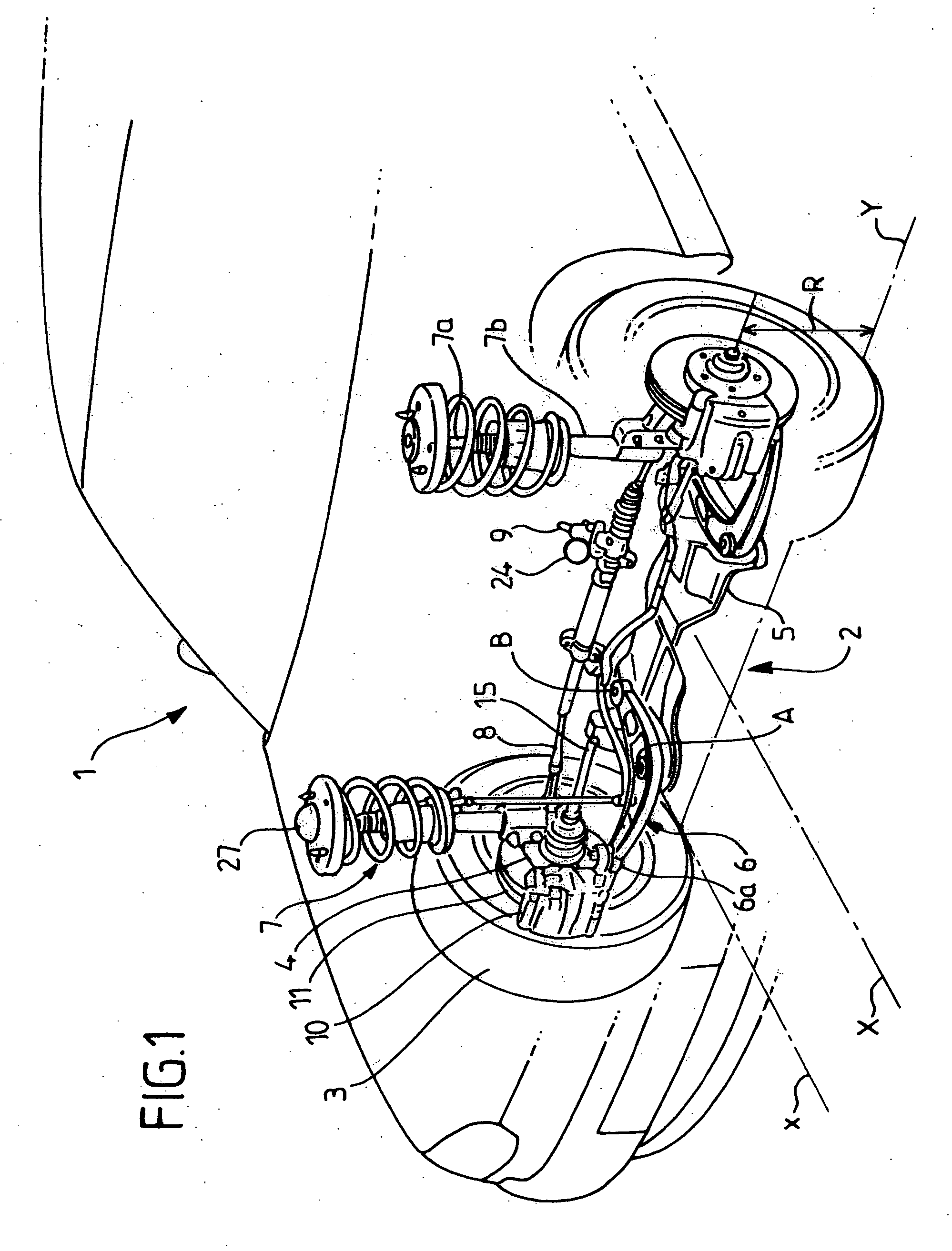
[0106] The first embodiment described above enables the determination of the longitudinal force exerted on the wheel 3 in very many situations, including complex driving situations in which a significant driving force and a significant resistance force are applied simultaneously to the wheel 3.

[0107] A second embodiment of the method and device for force determination will now be described, this being simpler than the first embodiment and suitable for determining the longitudinal force exerted on the wheel 3 in simple driving situations, namely when either the driving force or the braking force is zero or at least negligible.

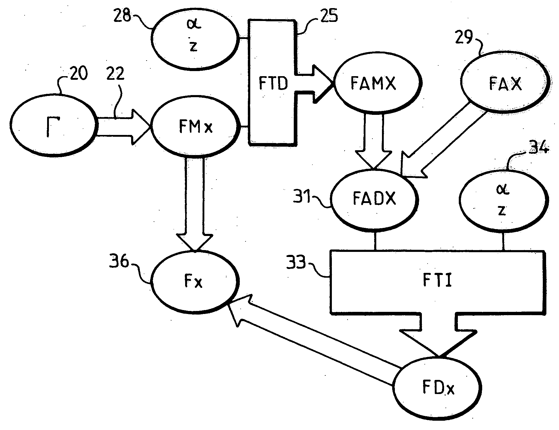
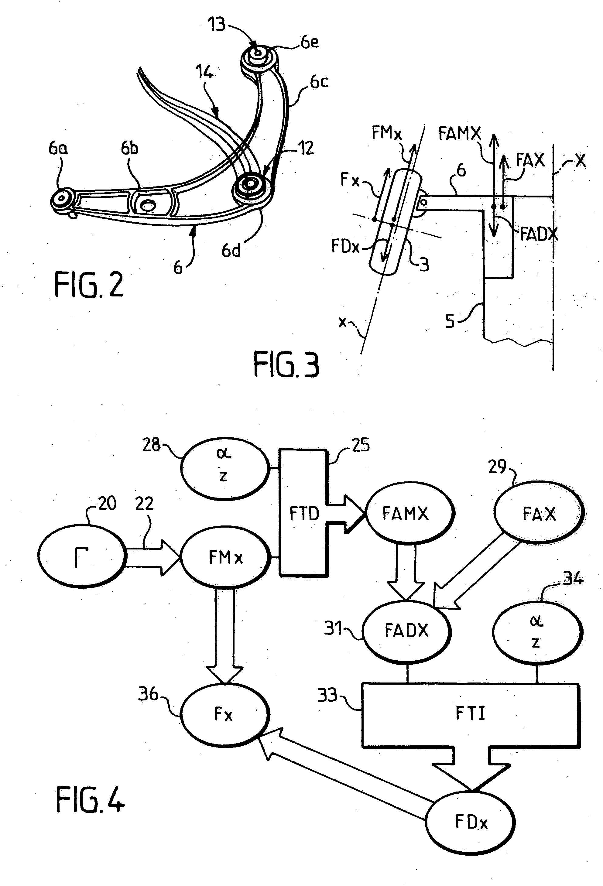
[0108] As mentioned earlier, when the driving force resulting from the drive torque Γ is zero or negligible compared with the resistance force, in particular compared with the force applied by the vehicle's braking system, the algorithm represented in FIG. 4 can be simplified by omitting stage 31. In this case, as indicated by the arrows 131a and 131b, the long...

second embodiment

[0113] An on-board electronic device 140 for implementing this simplified algorithm is represented in FIG. 6, in which, in the second embodiment, the components 23, 32 and 37 are omitted and elements represented by broken lines are added.

[0114] The measurement system 114 receives as an input a logic variable L which indicates whether the braking system of the wheel 3 is active or inactive. The measurement system 114 has two signal outputs 132a and 132b connected respectively to the neuronal network 35, and to a neuronal network 126 which is programmed to apply the transfer function which is the inverse of the function FTD, taking the drive torque Γ into account. The measurement system 114 has an output commutator (not shown), which switches as a function of the variable L to select the output 132a when the braking system is active, in which case the value of the force Fx is transmitted to the output interface 38 by the connection 114, and to select the output 132b when the braking s...


PUM


Abstract

A device and method are provided for determining a longitudinal force (Fx) exerted on a wheel of a motor vehicle by a ground surface supporting the wheel, the vehicle including connections means which connect the wheel to a body of the vehicle. An actual force (FAX) is measured at the level of at least one measurement point in the connection means. A force (FDx, Fx) is calculated which results from a transmission via the connection means from the at least one measurement point to the wheel, of a body-associated force (FADX, FAX), which depends at least on the actual force. The longitudinal force (Fx) exerted on the wheel by the ground surface is calculated as a function at least of the force (FDx; Fx) resulting from the transmission of the body-associated force.

Description

CROSS-REFERENCE TO RELATED APPLICATIONS [0001] This application claims benefit of French Patent Application No. 02 / 09718, filed Jul. 31, 2002, and Patent Cooperation Treaty International Application No. PCT / FR2003 / 002404, filed Jul. 30, 2003, both of which are incorporated herein by reference in their entirety. BACKGROUND OF THE INVENTION [0002] 1. Field of the Invention [0003] The present invention concerns a method and device for determining a force exerted on a wheel of a motor vehicle by a ground surface supporting the wheel, along a longitudinal direction of the wheel. [0004] 2. Description of Related Art [0005] On-board electronic systems are known, which are designed to assist the driver of a vehicle when he is in various types of difficult situations. The best known are without doubt the ABS anti-blocking systems and the ESP electronic regulation system for the dynamic behaviour of the vehicle. [0006] An ABS system acts on the braking system to prevent blocking of the wheels...

Claims


Application Information

Patent Timeline
Patent Type & Authority Applications(United States)
IPC IPC(8): B60G17/0195B60T8/172B60R16/02B60T8/174B60T13/74
CPCB60G17/0195B60T13/74B60G2202/312B60G2204/11B60G2204/113B60G2204/143B60G2400/64B60G2600/1879B60G2800/215B60G2800/22B60G2800/702B60G2800/92B60G2800/94B60T8/174B60G2200/142B60G2600/1878
Inventor HUCHARD, XAVIERLENOIR, JEAN-YVES
Owner MICHELIN & CO CIE GEN DES ESTAB MICHELIN
Why Eureka
Try Eureka