Light emitting display apparatus having excellent color reproducibility

US20050212407A1Active Publication Date: 2005-09-29SANYO ELECTRIC CO LTD

Image

  • Light emitting display apparatus having excellent color reproducibility
  • Light emitting display apparatus having excellent color reproducibility
  • Light emitting display apparatus having excellent color reproducibility

Examples


Embodiment Construction

[0034]

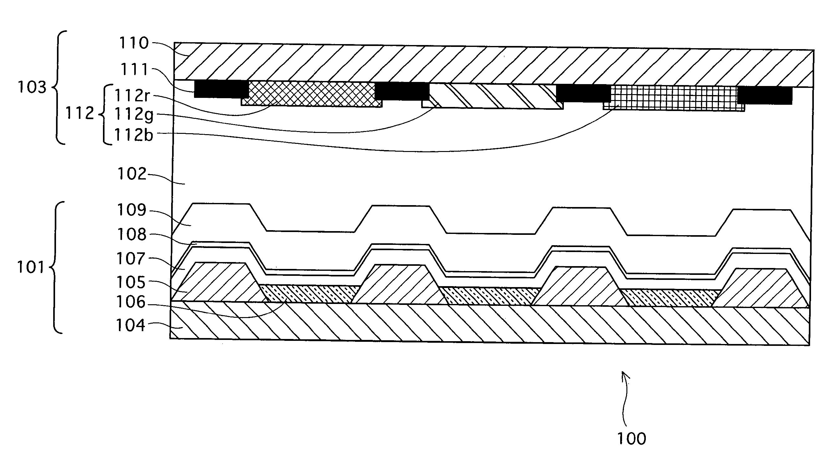
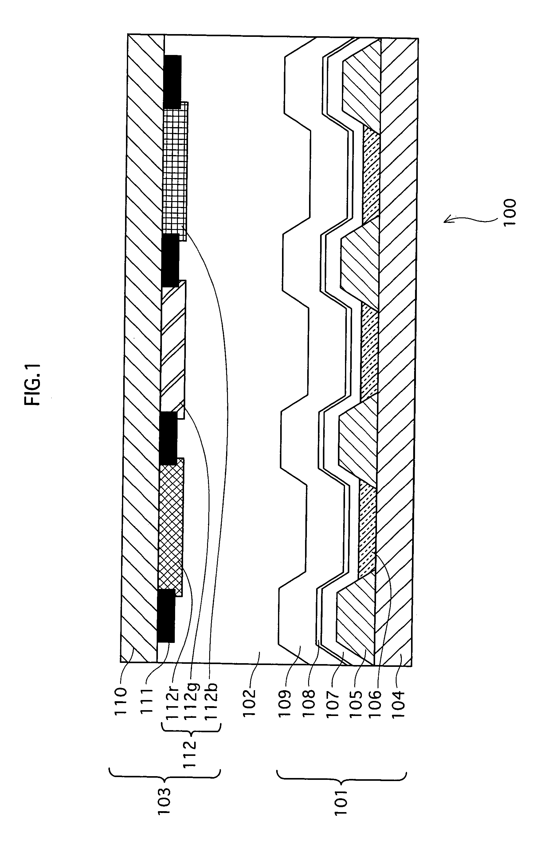
[0035]FIG. 1 is a schematic sectional diagram of an organic EL panel, which is one example of a light emitting display apparatus according to an embodiment of the present invention.

[0036] As FIG. 1 shows, an organic EL panel 100 of the present embodiment has a construction in which organic EL devices 101 that emit light themselves face a color filter substrate 103, with a sealing layer 102 therebetween.

[0037] In the color filter substrate 103, the color filter groups 112 are arranged on a main surface of a transparent substrate 110.

[0038] The transparent substrate 110 is made of glass having a thickness of about 0.5 mm-1.0 mm, but may alternatively be made of a plastic film.

[0039] The color filter groups 112 each include color filters 112r, 112g, and 112b, each of which transmits light of a corresponding one of three primary colors. The color filters 112r, 112g and 112b have a thickness of approximately no less than 1 μm but no more than 10 μm. In addition, black matrices ...


PUM

PropertyMeasurementUnit
Wavelengthaaaaaaaaaa

Abstract

Provided is a light emitting display apparatus that realizes color display, having: a plurality of organic light emitting devices, each of which includes an organic light emitting layer that synthesizes two or more complementary colors of light that are complementary to each other thereby producing white light, has a resonant structure by which a resonant wavelength is set to a predetermined wavelength, and outputs the white light via the resonant structure; and a plurality of wavelength selection units provided on a path through which the white light is outputted, each wavelength selection unit transmitting only light of a particular wavelength included in the outputted white light, where the predetermined wavelength substantially coincides with a wavelength corresponding to a primary color whose luminous intensity is, if without the resonant structure, the lowest of three primary colors included in the produced white light for the purpose of bringing the produced white light close to white light ideal for an image display light source.

Description

BACKGROUND OF THE INVENTION [0001] (1) Field of the Invention [0002] The present invention relates to a light emitting display apparatus, and particularly relates to a technology for improving color reproducibility. [0003] (2) Related Art [0004] Recently, light emitting display apparatuses that drive self luminous devices by means of thin film transistors (hereinafter also called “TFT”) are receiving attention as display devices having high efficiency, high definition, low power consumption, and high-speed response. [0005] Among such light emitting display apparatuses, those having a structure of causing organic light emitting devices stacked on a TFT substrate to emit light, and extracting the light highly efficiently in a direction of a so-called top side (i.e. opposite direction to a side of the TFT substrate on which TFTs, wiring, and so on, are provided) are under development. This type of light emitting display apparatus is called a top-emission organic electroluminescence pan...

Claims


Application Information

Patent Timeline
29 Sep 2005
Publication
US20050212407A1
IPC
H05B33/24; H01L27/32; H01L51/50; H01L51/52; H05B33/02; H05B33/12; H05B33/14; H05B33/22
CPC
H01L27/322; H01L51/5265; H01L51/5036; Y10S428/917; H10K59/38; H10K50/125; H10K59/876; H10K50/852
Inventors
MATSUSUE, NORIYUKI