Tunable antenna circuit, particularly for contactless integrated circuit reader

a technology of integrated circuits and antenna circuits, which is applied in the direction of antennas, antenna supports/mountings, and varying frequency control of electrical characteristics, can solve the problems of difficult to adjust the components of the antenna circuit bare-handed, affecting the resonance frequency, and manual tuning in certain conditions of us

Active Publication Date: 2005-10-06
WISEKEY SEMICONDUCTORS
View PDF5 Cites 40 Cited by
  • Summary
  • Abstract
  • Description
  • Claims
  • Application Information

AI Technical Summary

Benefits of technology

[0015] Briefly stated, the present invention comprises an antenna circuit including an integral filter or a phase shifter at the terminals of which a voltage appears the amplitude of which provides a pertinent indication capable of being used to tune the antenna circuit with precision, when the amplitude of the excitation signal is known. If the amplitude of the excitation signal is not known, the present invention provides for measuring two voltages at the terminals of the filter and for tuning the antenna circuit so that these two voltages have a determined amplitude ratio and a determined phase difference.

Problems solved by technology

Although this tuning is generally performed at the time of commissioning the antenna circuit, the latter is then subjected to variations in humidity and temperature that can substantially affect its resonance frequency.
Furthermore, a manual tuning can prove difficult in certain conditions of use.
Due to the poor weather conditions and the very low temperatures, it is difficult to adjust the components of the antenna circuit bare-handed, using a screwdriver.
However, a piece of equipment for measuring the phase Φ and the impedance Z is generally too costly and cumbersome to form an embedded piece of equipment.
This tuning method is simple and inexpensive, but the precision of it is mediocre.
Indeed, the voltage standing wave ratio provides an indication which, although it is pertinent, can be considered in the light of experience acquired, to be insufficient in itself to achieve reliable and precise tuning.
Furthermore, an adjustment of the antenna circuit based on the voltage standing wave ratio is long and difficult to find.

Method used


Image

  • Tunable antenna circuit, particularly for contactless integrated circuit reader
  • Tunable antenna circuit, particularly for contactless integrated circuit reader
  • Tunable antenna circuit, particularly for contactless integrated circuit reader

Examples


Embodiment Construction

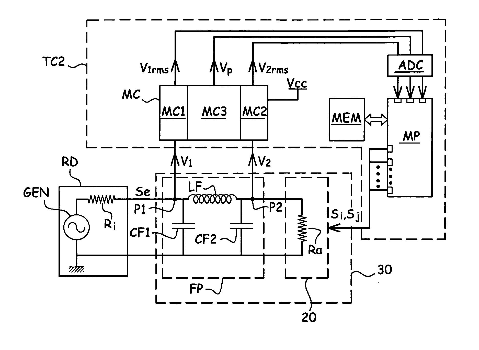
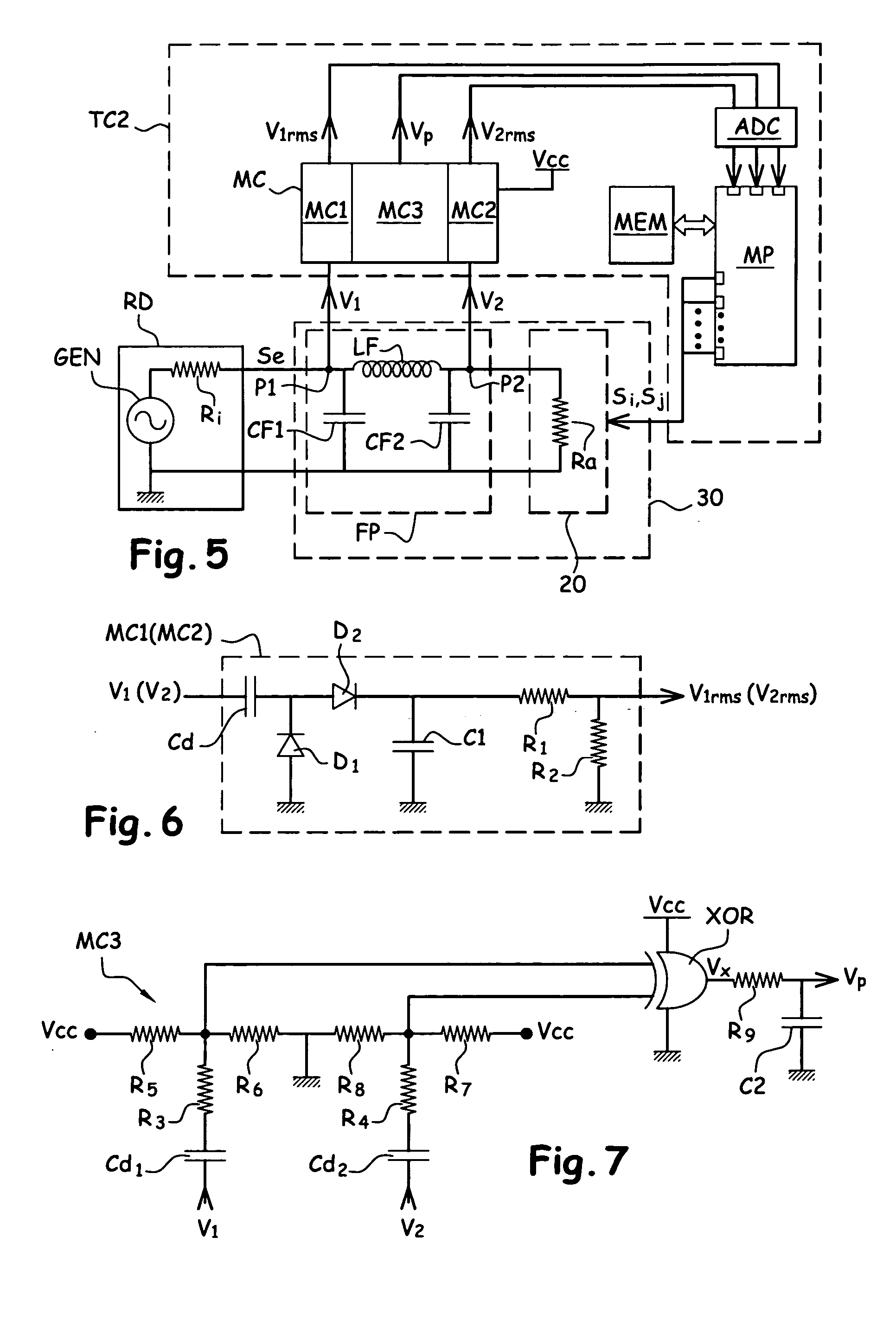
[0050]FIG. 5 represents a contactless integrated circuit reader RD comprising an antenna circuit 30 according to the present invention and an embedded tuning device TC2. The antenna circuit 30 and the tuning device TC2 can be produced on the same medium, such as on a same printed circuit board for example. They thus form a global antenna circuit integrating means for automatically tuning the actual antenna circuit.

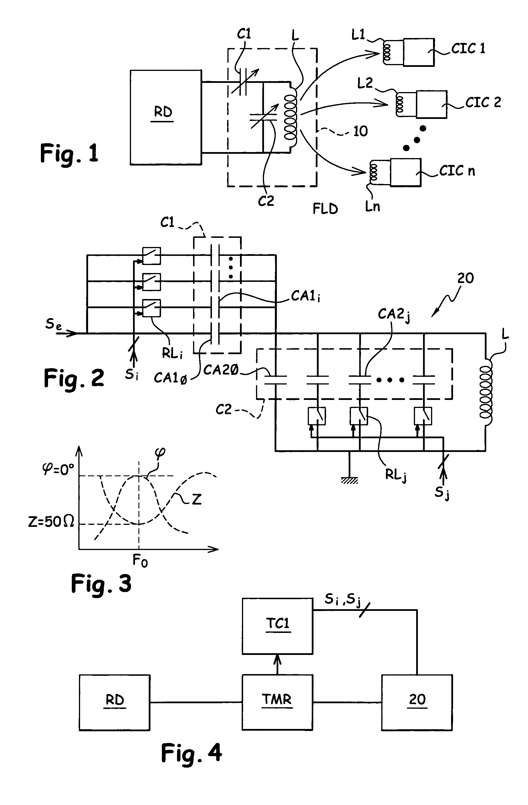
[0051] The antenna circuit 30 according to the present invention comprises an antenna circuit 20 and a filter FP. The antenna circuit 20 is an electrically tunable antenna circuit comprising electrically adjustable components. Its structure is for example that of the antenna circuit described above in relation with FIG. 2. The antenna circuit 20 is here represented tuned, in the form of a non-reactive resistor Ra of 50Ω.

[0052] The filter FP is connected to the input of the antenna circuit 20 and is an integral part of the antenna circuit 30. The input of the filter FP fo...


PUM


Abstract

An antenna circuit tunable to a determined resonance frequency, includes an antenna coil and adjustable components. The antenna circuit includes a filter having at least one point to tap an electric voltage the amplitude of which forms a pertinent indication for the tuning of the antenna circuit. To tune the antenna circuit, the adjustable components of the antenna circuit are adjusted so that the electric voltage has a determined amplitude.

Description

CROSS-REFERENCE TO RELATED APPLICATIONS [0001] This application is a continuation of International Application No. PCT / FR2003 / 003295, filed Nov. 5, 2003, which was published in the English language on May 7, 2004, under International Publication No. WO2004 / 045074 A1, and the disclosure of which is incorporated herein by reference.BACKGROUND OF THE INVENTION [0002] The present invention relates to inductive antenna circuits, particularly for contactless integrated circuit readers, and more particularly, to an antenna circuit tunable to a determined resonance frequency, comprising an antenna coil and adjustable components. The present invention further relates to a method for tuning such an antenna circuit. [0003]FIG. 1 schematically represents a contactless integrated circuit reader RD equipped with an antenna circuit 10 of the aforementioned type. The antenna circuit 10 comprises a coil L and adjustable components, such as two adjustable capacitors C1, C2. The antenna circuit receiv...

Claims


Application Information

Patent Timeline
Patent Type & Authority Applications(United States)
IPC IPC(8): H01Q1/22H01Q1/24H01Q9/00H03J1/00H03J7/04
CPCH01Q1/22H01Q1/2216H03J2200/10H03J7/04H03J1/0008
Inventor CHARRAT, BRUNO
Owner WISEKEY SEMICONDUCTORS
Why Eureka
Try Eureka