Light emitting module

a technology of light-emitting modules and modules, which is applied in the direction of discharge tube luminescnet screens, semiconductor/solid-state device details, coupling device connections, etc., can solve the problems of cumbersome handling of modules, faulty electrical connections, and stress, and achieves improved heat dissipation properties and convenient handling.

Inactive Publication Date: 2005-10-27
MORIYAMA SANGYO
View PDF2 Cites 61 Cited by
  • Summary
  • Abstract
  • Description
  • Claims
  • Application Information

AI Technical Summary

Benefits of technology

[0006] In view of such problems of the prior art, a primary object of the present invention is to provide a light emitting module which has

Problems solved by technology

However, in such a light emitting module, the bus bars in each bus bar pair are mechanically connected to each other by the LEDs, and this can result in stress being imposed upon electrical connections between the bus bars and the LEDs and may undesirably lead to faulty electrical connections.
Such a problem tends to be caused particularly when the light emitting module is being carried and thus makes the handling of the module cumbersome.
In thus formed light emitting module also, the bus bars in each bus bar pair are connected to each other by the light emitting elements (LEDs), and therefore, contains a problem that the stress imposed on the e

Method used


Image

  • Light emitting module
  • Light emitting module
  • Light emitting module

Examples


Embodiment Construction

[0078] In the following, preferred embodiments of the present invention will be described with reference to the drawings.

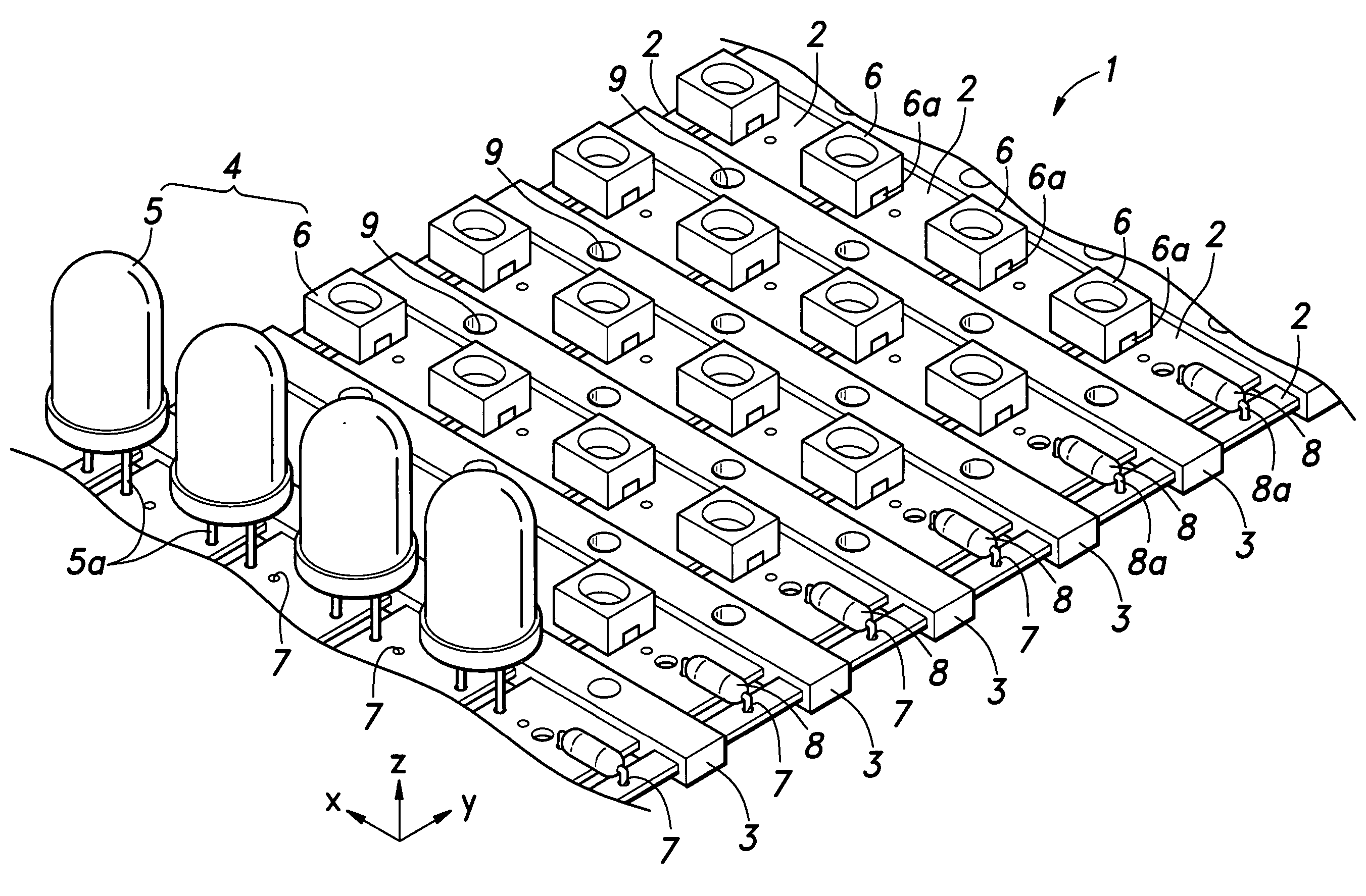
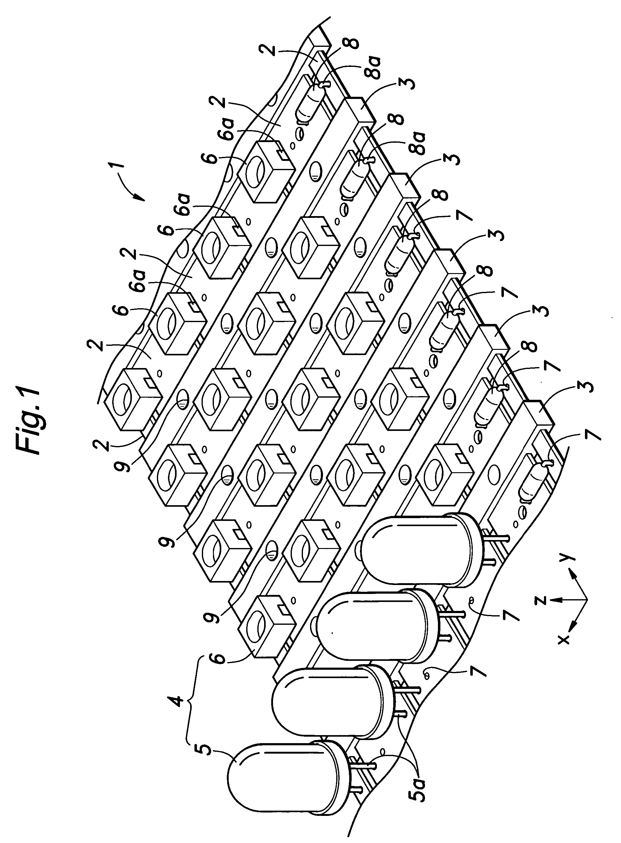
[0079]FIG. 1 is a partial perspective view showing one preferred embodiment of a light emitting module according to the present invention. As shown in the drawing, the light emitting module 1 comprises: a plurality (six in this embodiment) of thin plate-shaped conductors 2 spaced apart from each other in a first direction (in a direction of x-axis in FIG. 1) and extending in a second direction (in a direction of y-axis in FIG. 1) substantially perpendicular to the first direction; a plurality of insulating joint members 3 for mechanically joining the conductors 2; a plurality of in LEDs 4 mounted between adjoining conductors 2 to serve as light sources. The LEDs 4 are generally arranged in a matrix pattern at predetermined intervals in the first and second directions. The x-axis direction may sometimes be referred to as a column direction while the y-axis directi...


PUM


Abstract

The present invention provides a light emitting module, comprising: a plurality of thin plate-shaped conductors (2) spaced apart from each other in a first direction; at least one light source (4) connected between at least one pair of adjoining ones of said conductors; and at least one insulating joint member (4) for mechanically joining said plurality of conductors, wherein said at least one insulating joint member exposes both sides of at least a portion of said conductors where said light source is mounted.

Description

TECHNICAL FIELD [0001] The present invention relates to a light emitting module comprising one or more light sources and a method for manufacturing the light emitting module. BACKGROUND OF THE INVENTION [0002] It is conventionally known to provide a light emitting module comprising one or more light sources without using a printed circuit board, where the light sources are attached directly between a plurality of conductors extending substantially in parallel (see, e.g., U.S. Pat. No. 5,519,596). In the light emitting module shown in U.S. Pat. No. 5,519,596, a plurality of bus bar pairs are connected via electroconductive extendable joints, and a plurality of LEDs serving as light sources are connected between each bus bar pair by clinching, soldering, spot-welding or the like, to form a so-called matrix circuit comprising a plurality of LED parallel-connections that in turn are connected in series. Before attachment of the LEDs, the bus bars in each pair are connected to each other...

Claims


Application Information

Patent Timeline
IPC IPC(8): H01L33/48H05K1/00H05K3/20H05K3/32
CPCF21K9/00H05K1/0287H05K1/0393H05K3/202H05K3/326F21Y2105/001H05K2201/0397H05K2201/09118H05K2201/10106Y10S362/80H05K2201/0394F21Y2105/10F21Y2115/10
Inventor MORIYAMA, HIDEOYANAGITA, MUNEHIKOYANAGITA, KOICHI
Owner MORIYAMA SANGYO
Why Eureka
Try Eureka